background image

5

4

EN

EN

ELIS Z (models with timer)

Basic wiring information:

1)  Switch off the electrical circuit you will be working on.

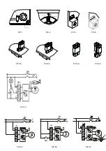
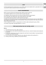
2)  Unscrew the screw on the side of the front panel and remove the cover, under which there is a terminal strip with 

three terminals.

3)  The terminals are labelled with the letters T (interruptible phase), L (fixed phase) and N (neutral phase).

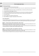
4)  Carefully review the wiring diagram in PIC 7a.

5)  Pull the power cables through the rubber bushing and connect them to the terminal strip per the diagram.

6)  Once connected to the terminal strip, fasten the power cables with a clamp near the bushing (PIC 1).

7)  Set the timer (Time).

8)  Set the jumpers for the selected mode (see below)

9)  After installation is complete, connect power and turn on the fan.

Timer settings (PIC 3.)

The timer is located under the front panel of the fan next to the terminal strip and is labelled as “Time”. Use a small 
screwdriver and carefully turn the adjustment screw to the left or right to set the timer from 15 seconds to 45 minutes. 

MODE 1 – activation using a separate switch with time delay shut-off

Wiring:

 From the separate switch, connect the black wire to the L terminal. Connect the brown switched wire to the T 

terminal and the blue neutral wire to the N terminal. Set the jumper in position 

5a

The fan is activated by pressing the separate single-pole switch and then runs continuously. Once the switch is turned 
off, the fan continues to run for the time set on the timer and then turns off. 

MODE 2 – activation after lights are turned off (PIC 7a and PIC 5b)

Wiring:

 From the light switch, connect the black wire to the L terminal. Connect the brown switched wire to the T 

terminal and the blue neutral wire to the N terminal. Set the jumper in position 

5b

.

The fan is connected to the light switch and is activated once the light is turned off and runs for the time set on the timer. 

ELIS ZW (models with timer and humidity control)

Basic wiring information:

1)  Switch off the electrical circuit you will be working on.

2)  Unscrew the screw on the side of the front panel and remove the cover, under which there is a terminal strip with 

three terminals.

3)  The terminals are labelled with the letters T (interruptible phase), L (fixed phase) and N (neutral phase)

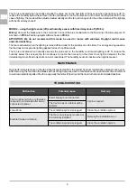
4)  Carefully review the wiring diagram in PIC 8a to PIC 8d, depending on the selected mode (see below).

5)  Pull the power cables through the rubber bushing and connect them to the terminal strip per the diagram.

6)  Once connected to the terminal strip, fasten the power cables with a clamp near the bushing (PIC 2).

7)  Set the timer (Time).

8)  Set the humidity control (Humidity).

9)  Set the jumpers I/II and A/B for the selected mode (see below)

10)  After the electrical wiring is installed, test the operation of the fan.

Timer settings (PIC 3.)

The timer is located under the front panel of the fan next to the terminal strip and is labelled as “Time”. Use a small 
screwdriver and carefully turn the adjustment screw to the left or right based on the designed timer setting, from 15 
seconds to 45 minutes. 

Humidity control settings (PIC 4.)

The humidity control is located under the front panel of the fan next to the terminal strip and is labelled as “Humidity”. 
Use a small screwdriver and carefully turn the adjustment screw to the left or right to set the switching humidity level for 
the fan, from 60% to 100%. 

MODE 1 – using the humidity sensor with time delay shut-off (PIC 8a)

Wiring:

 Connect the black wire to the L terminal. Connect the blue neutral wire to the N terminal. Position jumper I/II as 

shown in 

PIC 6b

. Position jumper A/B as shown in 

PIC 6a

.

The fan is activated once humidity in the space exceeds the set level. To reduce the humidity below the set level, the 
fan continues to run for the time set on the timer and then turns off. 

MODE 2 – using the humidity sensor with time delay shut-off and separate switch (PIC 8b)

Wiring:

 Connect the black wire to the L terminal. Connect the brown wire from switch S2 to the T terminal and the blue 

neutral wire to the N terminal. Position jumper I/II as shown in 

PIC 6b

. Position jumper A/B as shown in

 PIC 6a

.

The fan is activated once humidity in the space exceeds the set level. To reduce the humidity below the set level, the 
fan continues to run for the time set on the timer and then turns off. 

Switch operation:

 The fan is activated or turned off using switch S2 regardless of the selected mode.  If the fan is off, it 

is activated using the switch, after which the fan runs for the time set on the timer. It then turns off and returns to 
automatic mode. If the fan is running, use the switch to turn it off. 

MODE 3 – using the light sensor (on) and humidity sensor with time delay shut-off (PIC 8c)

Wiring: Connect the black wire to the L terminal. Connect the blue neutral wire to the N terminal. Position jumpers I/II as 
shown in 

PIC 6a

. Position jumpers A/B as shown in 

PIC 6a

ATTENTION:  We  do  not  recommend  this  mode  be  used  in  rooms  with  windows.  Daylight  could  cause 
unwanted switching. 

The fan runs for 45 seconds once the lights are turned on, and remains running while they are on. Turning off the lights 
activates the time delay shut-off and the fan runs for the time set on the timer.

Summary of Contents for ELIS

Page 1: ...ELIS GEBRAUCHSANWEISUNG HASZNÁLATI ÚTMUTATÓ ИНСТРУКЦИИ ЗА УПОТРЕБА NÁVOD K POUŽITÍ INSTRUKCJA OBSŁUGI NÁVOD NA POUŽITIE INSTRUCŢIUNILE USER MANUAL ...

Page 2: ...S1 М N L Time Humidity S1 S2 N L T Time Humidity М S1 М Time Humidity PIC 1 PIC 2 PIC 3 PIC 4 PIC 5a PIC 5b PIC 6a PIC 6b PIC 8a PIC 8b PIC 8c PIC 7a ...

Page 3: ...ns including children with reduced physical sensory or mental abilities or lack of experience and knowledge if they are not supervised or the person responsible for their safety has not provided them with the instructions for use The fan is designed for connection to a single phase 220 240 VAC system operating at a frequency of 50 Hz The enclosure rating is IP24 Operating temperature 1 to 40 C Wir...

Page 4: ...to the terminal strip and is labelled as Time Use a small screwdriver and carefully turn the adjustment screw to the left or right to set the timer from 15 seconds to 45 minutes MODE 1 activation using a separate switch with time delay shut off Wiring From the separate switch connect the black wire to the L terminal Connect the brown switched wire to the T terminal and the blue neutral wire to the ...

Page 5: ...nnect the black wire to the Lterminal Connect the blue neutral wire to the N terminal Position jumper I II as shown in PIC 6b Position jumperA B as shown in PIC 6a The fan is activated once humidity in the space exceeds the set level To reduce the humidity below the set level the fan continues to run for the time set on the timer and then turns off MODE 2 using the humidity sensor with time delay s...

Page 6: ...ted when humidity exceeds the value set on the humidity control and lighting is off To reduce the humidity below the set level the fan continues to run for the time set on the timer Once light is detected the fan immediately turns off and only starts once it is reactivated The humidity sensor is inactive when light is present MAINTENANCE Only perform maintenance on the fan when disconnected from the...

Page 7: ...ng durch Personen einschließlich Kinder mit verminderten körperlichen sinnlichen oder mentalen Fähigkeiten oder mit unzureichender Erfahrung und Kenntnis bestimmt oder sofern ihnen die für ihre Sicherheit verantwortliche Person keine Benutzungsanweisungen erteilt hat Der Lüfter ist für denAnschluss an einphasige 220 240 V Wechselspannung mit einer Frequenz von 50 Hz ausgelegt Die Schutzart ist IP2...

Page 8: ...emmblock und ist mit dem Wort Time gekennzeichnet Mit einem kleinen Schraubendreher und vorsichtigem Drehen nach links oder rechts lässt sich die Zeitschaltuhr von 15 Sekunden bis 45 Minuten einstellen MODUS 1 Starten über einen separaten Schalter mit Nachlauf PIC 7a und PIC 5a Anschluss Schließen Sie vom separaten Schalter den schwarzen Phasendraht an Klemme L an Schließen Sie den braunen Schaltd...

Page 9: ...raubendreher und einer vorsichtigen Links oder Rechtsdrehung lässt sich der Hygrostat auf die Luftfeuchtigkeit zwischen 60 und 100 einstellen bei der sich der Lüfter einschaltet MODE 1 über Feuchtigkeitssensor mit Zeitnachlauf PIC 8a Verdrahtung Schließen Sie das schwarze stromführende Kabel an Klemme L an Schließen Sie das blaue Neutralkabel an Klemme N an Setzen Sie Jumper I II wie in der PIC 6b...

Page 10: ...wolltenAusschaltung durch Tageslicht Der Lüfter startet nach dem Lichtausschalten und läuft für die an der Zeitschaltuhr eingestellte Zeit Beim Lichteinschalten für die Dauer von weniger als 90 Sekunden wird der Lüfter aus Energiespargründen nicht reagieren Außerdem startet der Lüfter wenn die Luftfeuchtigkeit den am Hygrostat eingestellten Wert überschreitet und das Licht aus ist Fällt die Luftfe...

Page 11: ...n k použití osobami včetně dětí se sníženými fyzickými smyslovými či mentálními schopnostmi nebo nedostatkem zkušeností a znalostí pokud nejsou pod dohledem nebo jim osoba odpovědná za jejich bezpečnost nepodala instrukce k používání Ventilátor je navržen pro připojení k jednofázovému střídavému proudu o 220 240 V s frekvencí 50 Hz Stupeň krytí je IP24 Provozní teplota 1 až 40 C ELIS modely bez ča...

Page 12: ...anelem ventilátoru vedle svorkovnice a je označen slovem Time Malým šroubovákem a opatrným otáčením doleva nebo doprava lze na časovači nastavit dobu v rozmezí 15 vteřin až 45 minut REŽIM 1 spuštění přes samostatný vypínač s doběhem PIC 7a a PIC 5a Zapojení Od samostatného vypínače zapojte černý fázový vodič do svorky L Hnědý spínací vodič zapojte do svorky Ta modrý nulový vodič do svorky N Jumper...

Page 13: ...dič do svorky L Modrý nulový vodič zapojte do svorky N Jumper I II umístěte podle obrázku PIC 6b JumperA B nastavte do pozice PIC 6a Ventilátor se zapne jakmile vlhkost v místnosti vzroste nad nastavenou hodnotu Po snížení vlhkosti pod nastavenou hodnotu ventilátor poběží po dobu nastavenou na časovači a pak se vypne REŽIM 2 přes čidlo vlhkosti s časovým doběhem a vlastním vypínačem PIC 8b Zapojen...

Page 14: ...odnotu nastavenou na hygrostatu a světlo je zhasnuté Po snížení vlhkosti pod nastavenou hodnotu poběží ventilátor po dobu nastavenou na časovači V případě rozsvícení se ventilátor okamžitě vypne a spustí se opět až po zapnutí Čidlo vlhkosti je během rozsvícení neaktivní ÚDRŽBA Údržbu ventilátoru provádějte pouze po odpojení od elektrické sítě Údržbu provádějte minimálně jednou ročně Po vyjmutí ven...

Page 15: ...to prístroj nie je určený na používanie osobami vrátane detí so zníženými fyzickými zmyslovými alebo mentálnymi schopnosťami alebo nedostatkom skúseností a znalostí ak nie sú pod dohľadom alebo ak im osoba zodpovedná za ich bezpečnosť neposkytla inštrukcie na používanie Ventilátor je navrhnutý na pripojenie k jednofázovému striedavému prúdu s napätím 220 240 V a frekvenciou 50 Hz Stupeň krytia je ...

Page 16: ...panelom ventilátora vedľa svorkovnice a je označený slovom Time Malým skrutkovačom a opatrným otáčaním doľava alebo doprava je možné na časovači nastaviť čas v rozmedzí 15 sekúnd až 45 minút REŽIM 1 spustenie cez samostatný vypínač s dobehom PIC 7a a PIC 5a Zapojenie Od samostatného vypínača zapojte čierny fázový vodič do svorky L Hnedý spínací vodič zapojte do svorkyTa modrý nulový vodič do svork...

Page 17: ...jenie vodičov Zapojte čierny fázový vodič do svorky L Modrý nulový vodič zapojte do svorky N Jumper I II umiestnite podľa PIC 6b JumperA B nastavte do pozície PIC 6a Ventilátor sa zapne ak vlhkosť v miestnosti vzrastie nad nastavenú hodnotu Po znížení vlhkosti pod nastavenú hodnotu ventilátor pobeží po nastavený čas na časovači a potom sa vypne REŽIM 2 cez snímač vlhkosti s časovým dobehom a vlast...

Page 18: ... hygrostate a svetlo je zhasnuté Po znížení vlhkosti pod nastavenú hodnotu pobeží ventilátor po nastavený čas na časovači V prípade rozsvietenia sa ventilátor ihneď vypne a spustí sa opäť až po zapnutí Snímač vlhkosti je počas rozsvietenia neaktívny ÚDRŽBA Údržbu ventilátora vykonávajte iba po odpojení od elektrickej siete Údržbu vykonávajte minimálne raz ročne Ventilátor po vybratí očistite jemno...

Page 19: ...eti A készüléket felügyelet nélkül gyermekek vagy magatehetetlen személyek nem használhatják illetve a készüléket csak olyan személy üzemeltetheti aki elolvasta és megértette a használati utasítást és a készülék használatáért felelősséget vállal Aventilátort 220 240 V egyfázisú 50 Hz es váltakozó áramra való csatlakozásra tervezték Avédettségi fok IP24 Üzemi hőmérséklet 1 és 40 C között Bekötés 1 ...

Page 20: ...t található és a Time felirat van rajta Egy kis csavarhúzóval és az időzítő óvatos balra vagy jobbra fordításával az időt 15 másodperctől 45 percig lehet beállítani 1 ÜZEMMÓD külön időzítő kapcsolóval történő indítás PIC 7a és PIC 5a Bekötés A külön kapcsolóról csatlakoztassa a fekete fázisvezetéket az L csatlakozóhoz Csatlakoztassa a barna kapcsolóvezetéket a T csatlakozóhoz a kék semleges vezeté...

Page 21: ...t az N csatlakozóhoz Helyezze el az I II jumpert a PIC 6b szerint Állítsa az A B átkötőt a PIC 6a ábra szerinti pozícióba A ventilátor akkor kapcsol be ha a helyiség páratartalma a beállított érték fölé emelkedik Amikor a páratartalom a beállított érték alá csökken a ventilátor az időzítőn beállított ideig működik majd kikapcsol 2 ÜZEMMÓD időzítővel és saját kapcsolóval ellátott páratartalom érzék...

Page 22: ...aladja a higrosztáton beállított értéket és a lámpa kialszik Amikor a páratartalom a beállított érték alá csökken a ventilátor az időzítőn beállított ideig működik Világítás esetén a ventilátor azonnal kikapcsol és csak bekapcsoláskor indul újra A páratartalom érzékelő inaktív amikor a lámpa világít KARBANTARTÁS A ventilátor karbantartását kizárólag az elektromos hálózatról történő leválasztást kö...

Page 23: ...enie nie jest przeznaczone do używania przez osoby łącznie z dziećmi z ograniczoną sprawnością fizyczną zmysłową lub psychiczną lub nieposiadające doświadczenia i wiedzy jeżeli nie są pod nadzorem lub osoba odpowiedzialna za ich bezpieczeństwo nie pouczyła ich o używaniu Wentylator jest przeznaczony do zasilania jednofazowym prądem przemiennym 220 220 240 V o częstotliwości 50 Hz Stopień ochrony IP...

Page 24: ... oznaczony słowem Time Ostrożnie obracając małym śrubokrętem w lewo lub w prawo można nastawić na timerze czas w zakresie od 15 sekund do 45 minut TRYB 1 włączanie przez samodzielny wyłącznik z opóźnieniem wyłączenia PIC 7a i PIC 5a Podłączenie Od samodzielnego wyłącznika podłączyć czarny przewód fazowy do zacisku L Brązowy przewód włączający podłączyć do zaciskuTa niebieski przewód zerowy do zaci...

Page 25: ...IC 8a Podłączenie przewodów Podłączyć czarny przewód fazowy do zacisku L Niebieski przewód zerowy podłączyć do zacisku N Jumper I II ustawić według rysunku PIC 6b JumperA B ustawić w pozycji PIC 6a Wentylator włączy się jak tylko wilgotność w pomieszczeniu wzrośnie ponad nastawioną wartość Po obniżeniu wilgotności wentylator będzie pracować przez czas nastawiony na timerze a następnie wyłączy się ...

Page 26: ...ać na włączenie światła trwające krócej niż 90 sekund Wentylator włączy się też jeżeli wilgotność przekroczy wartość nastawioną na higrostacie a światło jest zgaszone Po obniżeniu wilgotności poniżej nastawionej wartości wentylator będzie pracować przez czas nastawiony na timerze W razie włączenia światła wentylator natychmiast wyłączy się i włączy się znów po włączeniu Czujnik wilgotności podczas...

Page 27: ...an calificat Acest dispozitiv nu este destinat utilizării de către persoane inclusiv copii cu dizabilităţi fizice senzoriale sau mentale reduse sau fără experienţă şi cunoştinţe suficiente dacă nu sunt supravegheate sau dacă persoana care răspunde de siguranţa lor nu le a instruit cu privire la utilizarea aparatului Ventilatorul este proiectat pentru conectarea la curent alternativ monofazat de 220 2...

Page 28: ...ură şi este marcat cu cuvântul Time Cu o şurubelniţă mică şi rotirea atentă la stânga sau la dreapta pe cronometru poate fi setat intervalul de timp de la 15 secunde până la 45 de minute MODUL1 pornire cu întrerupător separat cu timp de oprire întârziat PIC 7a şi PIC 5a Conectare De la întrerupătorul separat conectaţi firul negru de fază la borna L Conectaţi firul de comutare maro la bornaTşi firul al...

Page 29: ...oprire întârziat PIC 8a Conectarea conductoarelor Conectaţi firul negru de fază la borna L Conectaţi firul albastru nul la borna N Plasaţi jumperul I II conform imaginii PIC 6b Setaţi jumperulA B în poziţia PIC 6a Ventilatorul va porni imediat ce umiditatea din încăpere va creşte peste valoarea setată După reducerea umidităţii sub valoarea setată ventilatorul va funcţiona pe perioada de timp setată ...

Page 30: ...a reacţiona la aprinderea luminii pe o durată mai scurtă de 90 de secunde De asemenea ventilatorul va porni dacă umiditatea depăşeşte valoarea setată pe higrostat şi lumina este stinsă După reducerea umidităţii sub valoarea setată ventilatorul va funcţiona pe perioada de timp setată pe cronometru În cazul aprinderii luminii ventilatorul se opreşte imediat şi porneşte din nou după stingere Senzorul...

Page 31: ...ва само от професионален електротехник Този уред не е предназначен за употреба от лица включително деца с намалени физически сетивни или умствени способности или с недостатъчен опит и знания освен ако не са под надзор или ако лицето отговарящо за тяхната безопасност не ги е инструктирало как да ползват уреда Вентилаторът е проектиран за свързване към монофазен променлив ток 220 240 V с честота 50 ...

Page 32: ...превключвателен проводник свържете към клема T а синия неутрален проводник към клема N Поставете джъмпера на позиция PIC 5a Вентилаторът се включва чрез натискане на самостоятелен еднопозиционен ключ и след това работи непрекъснато След изключването с ключа вентилаторът ще работи през времето зададено на таймера и след това ще се изключи РЕЖИМ 2 включване след изгасване на осветлението PIC 7a и PI...

Page 33: ...тавете джъмпера I II както е показано на PIC 6b Поставете джъмпераA B в позиция PIC 6a Вентилаторът се включва щом влажността в помещението се повиши над зададената стойност След намаляване на влажността под зададената стойност вентилаторът ще работи през времето настроено на таймера и след това ще се изключи Функции на ключа С ключа S2 вентилаторът може да се включи или изключи независимо от зада...

Page 34: ... Когато се включи осветлението вентилаторът се изключва веднага и тръгва отново чак когато бъде включен Докато осветлението е включено датчикът за влажност не е активен ПОДДРЪЖКА Извършвайте поддръжката на вентилатора само след като той е изключен от електрическата мрежа Извършвайте поддръжка поне веднъж годишно След като извадите вентилатора почистете го с мека кърпа напоена със слаб разтвор на в...

Page 35: ...35 ...

Page 36: ...ktronikus berendezések Sortowany odpad urządzenia elektryczne i elektroniczne Reciclarea deșeurilor Echipamente electronice și electrice Разделно изхвърляне на отпадъците електрически и електронни устройства The disposal of electronic and electrical products in unsorted municipal waste is forbidden Die Entsorgung des Productes darf nicht im unsortierten Siedlungsabfall erfolgen Po skončení doby po...

Reviews:

Related manuals for ELIS