


Mechanical Installation
7
Beam Mounting (Outdoor)
Reference Drawings:
Beam Mounting Procedure ...............................................................................
DWG-194664
Beam Mounting, Side View ...............................................................................
DWG-194671
Beam Mounting, Top View ................................................................................
DWG-194674
Beam Mounting, Rear View, Vertical Display ..................................................
DWG-194677
Beam Mounting, Rear View, Horizontal Display ..............................................
DWG-194678
Daktronics outdoor scoreboards are typically mounted on steel beams. Such beam-
mounted installations require that a qualified engineer provide specifications for both the
reinforced concrete footings and the steel support beams.
Two beams are required for each column of display modules. Beams must be set 4'-6"
(1372 mm) apart, center-to-center. Installations of vertical and horizontal displays are
shown in
DWG-194677
and
DWG-194678
.
Note:
Because every display is different in terms of module configuration, scoreboard
options, and environments, every installation will be unique.
Once the support beams are installed, refer to
DWG-194664
,
DWG-194671
, and
DWG-
194674
along with the instructions below to mount the display modules to the beams.
1�
Begin by attaching mounting brackets to the top and bottom of the lowest digit
module in the display. The brackets are fastened to the modules by inserting 10-
24 x 5/8" screws through the holes in each bracket and threading them into the
captivated nuts on the back of the module.
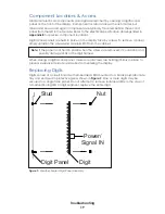
2�
With the brackets attached, position the module against the beam and secure it with
the 1/2-13 x 15" threaded rods, lock washers, and nuts provided. The rods do not go
through the beam but pass along either side; no drilling is required. The square nuts
go inside the bracket, while the lock washers and hex nuts are used outside the rear
mounting angles that straddle the back of each beam. Tighten the assembly with a
3/4" socket.
Note:
Do not over tighten the assembly as it may deform the brackets and angles.
3�
Attach the upper mounting brackets to the next module and position it against the
beams, on top of the first module.
4�
Insert screws through the upper brackets of the lower module to secure the bottom
of the upper module. This secures the brackets to the back of both modules.
5�
Secure the upper brackets of the upper module to the beams with bolts, washers,
and nuts as described in
Step 2
.
6�
Join the modules together at both ends by inserting screws up through the holes
in the top of the lower module into the captivated nuts in the bottom of the upper
module.
7�
The building process continues in the same manner for all remaining modules.
Caption modules are attached directly to their adjoining digit modules, similar to the
process outlined in
Step 6
; they do not accept beam mounting brackets.
Summary of Contents for SW-2001
Page 30: ...This page intentionally left blank ...
Page 32: ...This page intentionally left blank ...
Page 33: ......
Page 34: ......
Page 35: ......
Page 36: ......
Page 37: ......
Page 38: ......
Page 39: ......
Page 40: ......
Page 41: ......
Page 42: ......
Page 43: ......
Page 44: ......
Page 45: ......
Page 46: ......
Page 47: ......
Page 48: ......
Page 49: ......
Page 50: ......
Page 51: ......
Page 52: ......
Page 53: ......
Page 54: ...This page intentionally left blank ...
Page 56: ...This page intentionally left blank ...
Page 57: ......
Page 58: ......
Page 60: ......
Page 61: ......
Page 63: ......
Page 64: ......
Page 65: ......
Page 66: ......
Page 67: ......
Page 68: ......
Page 69: ......
Page 74: ......
Page 75: ......
Page 77: ......
Page 82: ...This page intentionally left blank ...


