background image


4.2  Display Access 

Maintenance and Troubleshooting 


4-2

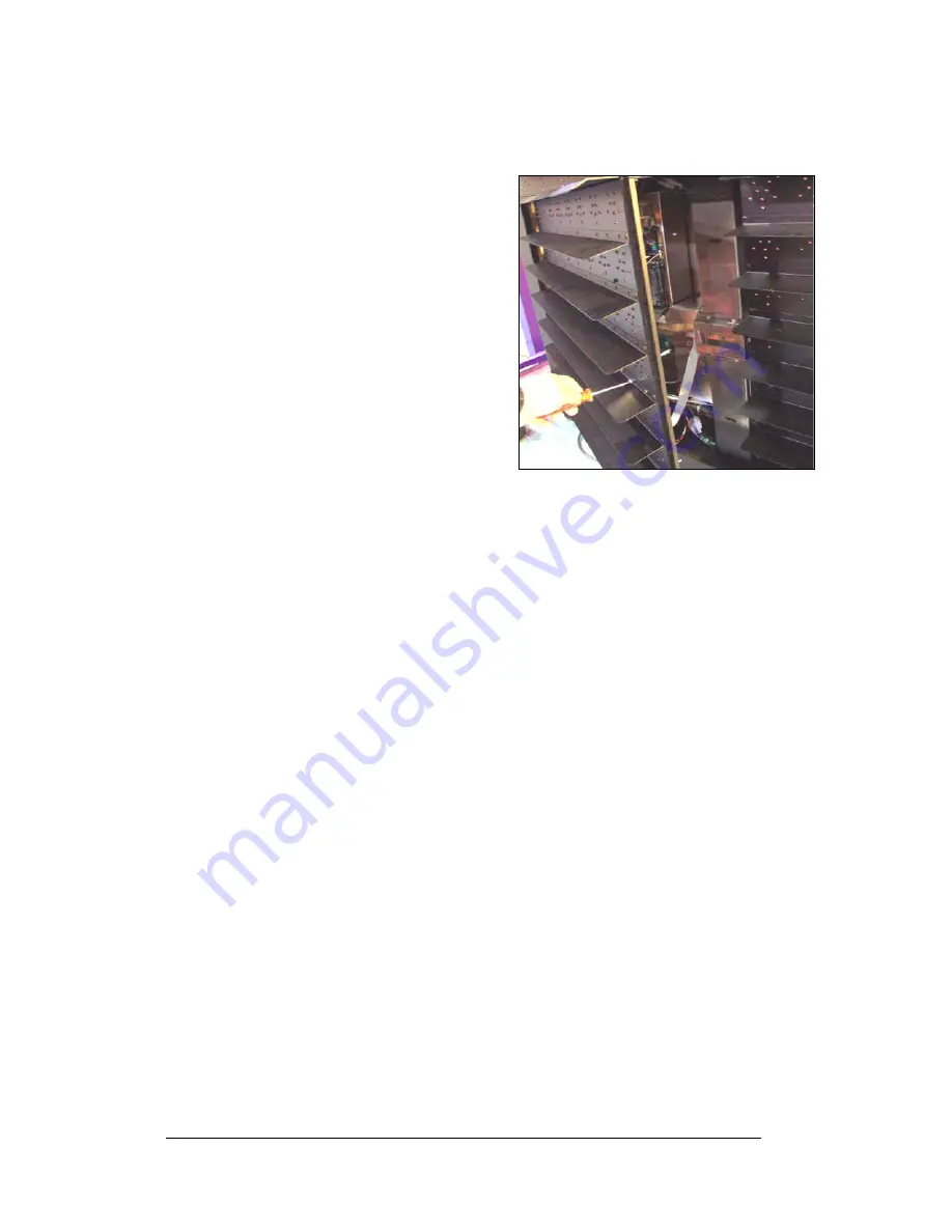
Display access for 89mm displays is 
normally from the front. To open the sign: 
 

1.


Locate the latch access fastener on 
the module. It is centered on the 
right side of the module. 

2.


With a #2 screwdriver, apply 
pressure to latch and turn it 
counter-clockwise. The module 
door will swing open to the left. 

3.


Interior display components may be 
accessed and the pixel strips may 
be removed. 

 
When closing a display, reverse the previous 
steps and take note of the following points: 


The weather-stripping on the back 
edge of the module is intact and in good condition for preventing water 
from seeping into the sign.  


Figure 18:  Opening the Display 


The module latches are fully engaged to create a water resistant seal around 
the edge of the module. The module 

must

 be firmly seated against the sign 

when the latches are fully engaged. 

4.3  Signal Summary 

Reference Drawings:


Schematic, AF-3400-(8-48X32-112)-89-Mono-*-* ....... 

Drawing A-177829 


The signal routing for the display can be summarized as follows: 
 

1.


Data from the controller computer, which runs Venus

®

 1500 software, 

travels via RS232, RS422, modem, fiber optic cable, radio, or Ethernet 
signal into the display. 

2.


From the controller, the signal then travels over a 20-conductor ribbon 
cables from the controller (J11 through J16 provides signal out) to J2 on the 
driver of the first column of modules in the display.


3.


Data exists at J1 and is relayed to J2 of the next driver board and so on, 
traveling down the entire row of modules.  


4.


For multiple face display or a display network, an RS422 (most typical) or 
fiber cable relays signal between the controller of the first display and the 
controller in the second display.


Note:

  The RS422 interconnection is not allowed when the input to the first 

display is Ethernet. 

 
5.


Refer to 

Drawing A-177829

 and 

Figure 19

 for further information. The 

drivers use this display data to control the LEDs.


Summary of Contents for Galaxy AF-3200 Series

Page 1: ...Galaxy Outdoor Series AF 3200 3400 89mm Display Manual ED15400 Rev 0 21 July 2005...

Page 2: ...ity for errors or omissions No part of this book covered by the copyrights hereon may be reproduced or copied in any form or by any means graphic electronic or mechanical including photocopying taping...

Page 3: ...ignal Connection 3 4 3 5 Power 3 4 Grounding 3 5 Power Installation 3 6 Main Disconnect 3 6 3 6 Signal Termination from Computer to Sign 3 6 3 7 Optional Temperature Sensor 3 7 3 8 First Time Operatio...

Page 4: ...Table of Contents ii Appendix A Reference Drawings A 1 Appendix B Signal Converter B 1 Appendix C Optional Temperature Sensor C 1...

Page 5: ...correct 2 2 Figure 8 Ribbon Cable Connector 3 1 Figure 9 Termination Block 3 1 Figure 10 Phoenix Connector 3 1 Figure 11 Mate N Lok Connector 3 2 Figure 12 Fiber Optic Cable 3 2 Figure 13 RJ45 Connect...

Page 6: ......

Page 7: ...cluded within the manual Appendix B includes information about the signal converter Appendix C includes information about the Optional Temperature Sensor Daktronics identifies manuals by an ED number...

Page 8: ...perly grounded with an earth ground electrode at the display 3 Disconnect power when servicing the display 4 Do not modify the display structure or attach any panels or coverings to the display withou...

Page 9: ...wing A 183906 Shop Drawings Refer to Appendix A Daktronics 89mm AF 3200 3400 Galaxy displays are designed and manufactured for performance reliability easy maintenance and long life The pixels have an...

Page 10: ...The COM port controls the sign through a 9 serial connector Controller The display s controller is the brains of the display The controller receives translates and activates the signal information fr...

Page 11: ...l strips louvers and a driver Refer to Figure 3 for identification of these parts Figure 3 8x8 Pixel Module Front and Rear Network Consists of multiple signs connected to each other Pixel Cluster of L...

Page 12: ...t J_ _ stands for a power or signal jack P_ _ represents a power or signal plug for the opposite jack Finally drawings commonly have Daktronics part numbers You can use those part numbers when request...

Page 13: ...nting of this display Read both the mechanical and electrical installation sections of this manual before beginning any installation procedures 2 2 Support Structure Design Support structure design de...

Page 14: ...er minute per module 28 x 28 active area Failure to comply with these requirements voids the Galaxy display warranty 2 4 Lifting the Display The top of the display has eyebolts to lift the unit Do not...

Page 15: ...ural engineer review the number of attachment points needed and the wall structure to ensure both meet all national and local codes Daktronics recommends using all clip angles as attachment points 1 C...

Page 16: ...Electrical Installation 2 4 2 6 Optional Temperature Sensor If you have an optional temperature sensor to be used with your display see Appendix C for mounting and signal connections...

Page 17: ...des to unlock and remove the jack Figure 9 Termination Block Before replacing a ribbon cable connector spray it with DeoxIT contact cleaner to remove any foreign matter that may cause signal problems...

Page 18: ...ck depress the small clip on the underside of the plug Figure 13 RJ45 Connector Before replacing an RJ connector spray it with DeoxIT contact cleaner to remove any foreign matter that may cause signal...

Page 19: ...nd sunlight resistant Note Daktronics engineers strongly recommend that the quick connect cable be secured to protect it from weather or vandalism 5 Earth ground enclosures that use wire signal cable...

Page 20: ...ol computer to the display at this time Be sure to run the power and signal cables in separate conduit 3 5 Power Reference Drawings Layout Pnl Bd 8 48x32 112 89mm 1 Phase Drawing A 175209 Layout Pnl B...

Page 21: ...lectrode must be installed for each display face The grounding electrode is typically one grounding rod for each display face Other grounding electrodes as described in Article 250 of the National Ele...

Page 22: ...pply connection to the display Provide a main disconnect for each supply circuit to the display You must locate the means of disconnection in a direct line of sight from the display or outline lightin...

Page 23: ...etween controllers Appendix C explains the connections for a temperature sensor Figure 17 RS422 Interconnection RS422 Interconnection Face A RS422 Out TB3 Field Cabling Face B RS422 IN TB2 Pin 1 GND S...

Page 24: ...ddress HW XX 8 Software Address SW XX 9 IP Address default 172 16 192 25 10 Subnet Msk default Msk 255 255 0 0 11 COM1 Configuration C1 V15 Modem C1 V15 If a Modem is present 12 COM 2 Configuration C2...

Page 25: ...provides a listing of all tools needed in order to perform maintenance work on your display Signal Routing Summaries give a basic explanation of how the signal travels through the sign Power Routing...

Page 26: ...are fully engaged 4 3 Signal Summary Reference Drawings Schematic AF 3400 8 48X32 112 89 Mono Drawing A 177829 The signal routing for the display can be summarized as follows 1 Data from the controlle...

Page 27: ...es power the modules in a monochrome amber and the RGB displays Refer to Drawings A 158225 A 184245 and A 177829 for power supply wiring information 4 Power is also sent to the fans which cool the dis...

Page 28: ...place the line filter by first labeling and removing all connecting wires and then releasing the attachment hardware Refer to Drawing A 158472 Install the new filter and reference Drawing A 177829 for...

Page 29: ...ck of the module To remove a driver board Figure 20 Driver Board 1 Open the display as described in Section 4 2 2 Loosen the two 10 screws holding the driver cover in place 3 Lift the cover off from t...

Page 30: ...conn J1087 Drawing B 177838 The controller sends data to the modules Refer to the signal summary in Section 4 3 for more information and to the component location drawings for the position of the con...

Page 31: ...9 240 F 0 Diagnostic LEDs are located on the controller the table below shows what each LED denotes Maintenance and Troubleshooting CPU LED Color Function Operation DS1 Red CAN TxD Flashes when contro...

Page 32: ...isplay 4 10 Power Supplies Reference Drawings Schematic Power Supply Configurations Drawing A 158225 Schematic Power Supply Assembly Drawing A 184245 The LED power supplies are identified as assemblie...

Page 33: ...Component Layout AF 3190 X 89mm Drawing B 181666 A thermostat controls when the ventilation fans operate in the display Refer to Drawing B 181666 for the location of the thermostat The ventilation fa...

Page 34: ...first driver on the left side of the first module that is not working Replace the second driver that is not working Replace the power supply assembly to the first module that is not working One row o...

Page 35: ...is complete the display will blank A single pixel will flash in the lower right hand corner of the display to show that the display has power but no messages are currently running 4 17 Replacement Pa...

Page 36: ...other Daktronics service When you call the Help Desk a trained service technician will work with you to solve the equipment problem You will work together to diagnose the problem and determine which r...

Page 37: ...l the Daktronics Help Desk for the RMA This expedites repair of your component when it arrives at Daktronics Packaging for Return Package and pad the item well so that it will not be damaged in shipme...

Page 38: ......

Page 39: ...RGB Drawing A 183906 Schematic Power Supply Assembly Drawing A 184245 Block Diagram Power AF 3190 89mm Drawing B 175203 Cntrlr Galaxy 8 Conn J1087 Drawing B 177838 Module Panel AF 3190 8x8 89mm A Draw...

Page 40: ......

Page 41: ......

Page 42: ......

Page 43: ......

Page 44: ......

Page 45: ......

Page 46: ......

Page 47: ......

Page 48: ......

Page 49: ......

Page 50: ......

Page 51: ......

Page 52: ......

Page 53: ......

Page 54: ......

Page 55: ......

Page 56: ......

Page 57: ......

Page 58: ......

Page 59: ......

Page 60: ......

Page 61: ......

Page 62: ......

Page 63: ......

Page 64: ......

Page 65: ......

Page 66: ......

Page 67: ......

Page 68: ......

Page 69: ...Appendix B Signal Converter B 1 Appendix B Signal Converter...

Page 70: ......

Page 71: ...Appendix C Optional Temperature Sensor C 1 Appendix C Optional Temperature Sensor...

Page 72: ...ensor housing 0A 1151 0005 Temperature sensor 0P 1247 0008 4 pin Mal Conxall cable W 1819 22 AWG 2 pair shielded cable W 1234 30 foot extension cable W 1820 100 foot extension cable W 1821 200 foot ex...

Page 73: ...3 Route cable up to the quick connect jack on the back of the display and plug into J31 Refer to Section 1 3 for an example of connection 1 3 Temperature Signal Connection Three options for signal co...

Page 74: ...nal block in the CAN temperature sensor housing 3 Cut the cable to the desired length and reattach to the temperature sensor terminal block in the CAN temperature sensor housing Refer to the table and...

Page 75: ...elded cable to connect the sensor to the 8 position terminal block in the display labeled CAN US DS A31 TB4 Connect to the controller as shown in Figure 8 3 Open the temperature sensor housing by remo...

Page 76: ...ete If the interconnect cable was not used a 4 conductor shielded cable is needed to terminate the temperature sensor from side one to side two One end terminates at the CAN US DS 8 position terminal...

Page 77: ...r details on sensor housing disassembly 2 Label the wires connected to the temperature sensor board and then disconnect the cable from the temperature sensor terminal block in the temperature sensor h...

Page 78: ......

Page 79: ......

Reviews: