background image

Engine Starting

For cold-weather starting, refer to "Cold Weather
Starting" later in this chapter.

Whenever you start an engine, watch for any signs
of engine problems. If the engine vibrates, misfires,
or makes unusual noises, turn the engine off as soon
as possible and determine the cause of the problem.
Frequently, engine damage may be avoided by a
quick response to early indications of problems.

NOTICE

When starting a vehicle equipped with a manual
transmission and clutch lockout switch, the
clutch pedal must be fully depressed during the
entire start sequence. Failure to do so can cause
the pinion to release and re-engage, which could
cause ring gear and starter pinion damage.

If a vehicle does not start on the first attempt,
make sure that the engine has completely
stopped rotating before reapplying the starter
switch. Failure to do so can cause the pinion to
release and re-engage, which could cause ring
gear and starter pinion damage.

Moving a vehicle with the starter and/or using the
starter to bump the engine for maintenance pro-
cedures is strictly prohibited. Use of these meth-
ods to bump the engine over or move the vehicle
can cause the pinion to release and re-engage,
which could cause ring gear and starter pinion
damage.

Ring gear and starter pinion damage caused by
improper starting procedures is not warrantable.

Pre-Start

NOTE: These pre-start steps apply to all en-
gines.

1.

Perform the engine pretrip inspection and daily
maintenance checks in

Chapter 11

.

2.

Set the parking brake.

3.

For manual transmissions, place the transmis-
sion in neutral and disengage the clutch.

For automatic transmissions, make sure the
transmission shift control is in neutral or park.

NOTE: On vehicles equipped with a neutral start
switch, the transmission must be in neutral be-
fore the engine can be started. For air start sys-
tems, check the air supply before starting the
engine. There must be 100 psi (689 kPa) of air
pressure available.

4.

Turn the ignition switch to the ON position
(

Fig. 7.14

). All the electronic gauges on the ICU

(instrumentation control unit) complete a full
sweep of their dials, the warning and indicator
lights light up, and the buzzer sounds for three
seconds.

A

B

11/08/2010

f470540a

NOTE: STOP engine light illuminates. Engine power
limited, speed limit of 5 mph (8 km/h)
A. DEF Warning Lamp (flashing)
B. DEF Lightbar (one bar flashing red)

Fig. 7.13, DEF Empty and Ignored Warning

09/12/2001

f610509

Fig. 7.14, Ignition Switch Positions

Engines

7.9

Summary of Contents for Freightliner

Page 1: ...e if an air bag is installed or if the vehicle features a collision avoidance system etc Customer Assistance Center Having trouble finding service Call the Customer Assistance Center at 1 800 385 4357 or 1 800 FTL HELP Call night or day weekdays or weekends for dealer referral vehicle information breakdown coor dination or Fleetpack assistance Our people are knowledgeable professional and committed...

Page 2: ...system or transmitted in any form by any means electronic mechanical photocopying recording or otherwise without the prior written per mission of Daimler Trucks North America LLC For additional information please contact Daimler Trucks North America LLC Service Systems and Documentation P O Box 3849 Portland OR 97208 3849 U S A or refer to www Daimler TrucksNorthAmerica comand www FreightlinerTruc...

Page 3: ...2 1 3 Instruments 3 1 4 Controls 4 1 5 Cab Features 5 1 6 Heater Ventilator and Air Conditioner 6 1 7 Engines 7 1 8 Drivetrain 8 1 9 Steering and Brake Systems 9 1 10 Fifth Wheels and Trailer Couplings 10 1 11 Pretrip and Post Trip Inspections and Maintenance 11 1 12 Cab Appearance 12 1 13 In an Emergency 13 1 14 Headlight Aiming 14 1 15 Hybrid Electric Vehicle 15 1 16 Natural Gas Vehicle 16 1 Ind...

Page 4: ...le Identification Vehicle Specification Decal 1 1 Federal Motor Vehicle Safety Standard FMVSS Labels 1 1 Canadian Motor Vehicle Safety Standard CMVSS Labels 1 2 Tire and Rim Labels 1 2 EPA Emission Control 1 2 ...

Page 5: ...on after completion of the vehicle a certifica tion label similar to that shown in Fig 1 2 must be attached by the final stage manufacturer This label will be located on the left rear door post and certifies f080021 11 21 96 USE VEHICLE ID NO WHEN ORDERING PARTS WHEELBASE ENGINE NO TRANS NO FRT AXLE NO REAR AXLE NO REAR AXLE NO RATIO FOR COMPLETE PAINT INFORMATION SEE VEHICLE SPECIFICATION SHEET MANU...

Page 6: ...tain Freightliner incomplete vehicles may be produced with incomplete noise control hardware Such vehicles will not have a vehicle noise emission control information label For such vehicles it is the final stage manufac turer s responsibility to complete the vehicle in conformity to U S EPA regulations 40 CFR Part 205 and label it for compliance EPA07 and EPA10 Emission Control To meet EPA07 and EP...

Page 7: ...mbing or aftertreatment in any way that would bring the engine out of compliance with certification requirements Ref 42 U S C S7522 a 3 It is the owner s responsibility to maintain the vehicle so that it conforms to EPA regulations Vehicle Identification 1 3 ...

Page 8: ...nd Handles 2 1 Grab Handles and Access Steps 2 1 Cab Entry and Exit Vehicles With Two Steps 2 2 Cab Entry and Exit Vehicles With One Step 2 4 Back of Cab Access 2 5 Battery Access 2 6 Hood Opening and Closing 2 7 Fuse Identification 2 8 ...

Page 9: ...s door Close the door if it is open Push down the inside lock button Fig 2 2 Close the door To open the door from the inside lift up on the door lever This will unlatch the door whether or not it is locked If it is open close the door by pulling the inner door grab handle To lock either door from inside the cab slide the lock button downwards Fig 2 3 To unlock the door without unlatching it push t...

Page 10: ... hoses or other back of cab equipment Careless ness could cause a person to trip and fall with possible injury Use the cab access system grab handles access steps and steering wheel to enter or exit the cab Entering from the Driver s Side To enter the cab from the driver s side do the follow ing steps Fig 2 4 1 Use the door pull handle to open the driver s door and place anything that you are carr...

Page 11: ...o take with you NOTE You can also use the inner door grab handle if available as a support when getting up or down from the bottom step Entering from the Passenger s Side To enter the cab from the passenger s side do the following steps Fig 2 5 1 Open the passenger s door and place anything that you are carrying in the cab 2 Grasp the B pillar grab handle on the door with both hands 3 Place your l...

Page 12: ...d lead to a fall and personal injury Be careful not to get hands or feet tangled in hoses or other back of cab equipment Careless ness could cause a person to trip and fall with possible injury Use the cab access system grab handles access steps and steering wheel to enter or exit the cab Entering from the Driver s Side To enter the cab from the driver s side do the follow ing steps Fig 2 4 1 Use ...

Page 13: ... in when exiting the cab Do not at tempt to exit with your back to the cab as you would going down a flight of stairs It is easier to slip or lose your balance If you slip when exiting in this way there is a greater likelihood of per sonal injury 2 Grasp the A pillar cover grab handle with both hands then place your right foot on the step while standing up from the seat facing inward 3 Place your ...

Page 14: ...le 5 Step onto the deck plate Climbing Down from Back of Cab To climb down from the back of cab area 1 Grasp the sidewall grab handle with both hands 2 Step one foot at a time onto the top step 3 Move your upper hand to a lower position on the grab handle 4 Move one foot to the bottom step 5 Move your upper hand to a lower position on the grab handle 6 Step to the ground with your upper foot first ...

Page 15: ...e engine and remove the negative battery cables NOTE Whenever battery power is discon nected clocks and electronically tuned radios must be reset Hood Opening and Closing The hood can be raised to a full open position A tor sion bar helps you to raise the hood and to lower it to the operating position Hood restraint cables pre vent the hood from overtravel A hood damper limits the closing speed In...

Page 16: ...ly Red 10 Amp F2 Blower Motor Green 30 Amp F3 Engine ECU Yellow 20 Amp F4 Transmission Control Unit Green 30 Amp F5 Ignition Switch Tan 5 Amp F6 Spare F7 Bulkhead Module Green 30 Amp F8 ICU Red 10 Amp F9 Transmission Control Unit Yellow 20 Amp F10 Door Locks optional Red 10 Amp F11 Mirrors optional Blue 15 Amp F12 Radio Diagnostics Yellow 20 Amp F13 Chassis Module Green 30 Amp F14 L H Power Window...

Page 17: ...cro relays 09 25 2001 f543935 1 2 1 Bulkhead Module 2 Main Fuse Box Fig 2 11 Location of the Main Fuse Box 10 25 2001 f543936 Fig 2 12 Main Fuse Box Diagram 09 28 2004 f544528 Fig 2 13 Trailer Fuse Box Diagram 10 07 2004 f544541 Fig 2 14 Taillight Fuse Box Diagram Vehicle Access 2 9 ...

Page 18: ...3 Instruments Instrumentation Control Unit 3 1 Warning and Indicator Lights 3 5 Standard Instruments 3 9 Optional Instruments 3 12 Overhead Instrument Panel 3 15 ...

Page 19: ...l The air gauges operate mechanically The ICU3 also has the capability to drive up to six independent stand alone gauges such as those in stalled on the auxiliary dash panel Figure 3 2 shows a typical dash panel layout Dash Message Center The dash message center houses all of the standard and optional warning and indicator lamps as well as the driver display screen The display screen has a f610525...

Page 20: ...ys them if any one after the other until the engine is started or the ignition switch is turned off If there are no active fault codes the driver display screen displays the odometer When the ignition is first turned on all the electronic gauges complete a full sweep of their dials the warning and indicator lamps illuminate and the au dible warning sounds for three seconds On EPA10 compliant vehicl...

Page 21: ...d with the engine running or the mode reset button is pressed POWER ON PARK BRAKE IGNITION ON HEADLIGHTS ON RELEASE PARK BRAKE f040804 10 26 2009 RELEASED MOVING FAULT CODE SCREEN IF NO FAULTS WERE DETECTED ELECTRONIC GAUGE NEEDLES SWEEP WARNING INDICATOR LIGHTS COME ON BUZZER SOUNDS IF FAULT DETECTED ICU PERFORMS SELFTEST 123456 7 ABS 11 ODOMETER SCREEN 123456 7 12 3 VOLTS 123456 7 12 3 VOLTS MI ...

Page 22: ...wing screens i Trip distance ii Trip hours iii Outside temperature iv Select screen v Temperature alert screen vi Diagnostic screen vii Clear screen with less than 254 miles viii Engine miles ix Engine hours x Setup screen xi Back to odometer Trip Miles To reset trip miles and or trip hours to zero press the mode reset button for one second or longer Miles or Kilometers To toggle between MI miles ...

Page 23: ...TOP engine lamp will illuminate NOTE If the CHECK engine lamp illuminates during vehicle operation take the vehicle di rectly to an authorized Freightliner service facil ity WARNING When the red STOP engine lamp illuminates most engines are programmed to shut down au tomatically within 30 seconds The driver must immediately move the vehicle to a safe location at the side of the road to prevent cau...

Page 24: ...sed 21 Air Restriction Indicator 22 Left Turn Signal 23 Low Battery Voltage Warning 24 Driver Display Screen 25 High Beam Headlights Indicator 26 Low Air Pressure Warning 27 Right Turn Signal Fig 3 7 Pre EPA07 Dash Message Center f610850 10 18 2006 1 2 3 4 8 9 10 14 15 5 6 7 11 12 13 18 19 17 16 ABS ABS OPT OPT OPT OPT OPT OPT OPT OPT OPT Typical installation shown Location of legends installed in...

Page 25: ...w 5 mph 8 km h It does not signify the need for service it only alerts the vehicle operator to high exhaust temperatures when a regen is in progress DPF Status Solid illumination indicates a regen is required Change to a more challenging duty cycle such as highway driving to raise exhaust temperatures for at least twenty minutes or perform a parked regen Blinking indicates that a parked regen is r...

Page 26: ...or Fuel Filter Restriction Indicates the fuel filter is clogged and requires service Low Battery Voltage Indicates that battery voltage is 11 9 volts or less Check Transmission Indicates an undesirable transmission condition Transmission Overheat Indicates high transmission temperature NO CHARGE No Charge Indicates an alternator charge output failure Engine Brake Indicates the engine brake is engag...

Page 27: ...of the vehicle will be limited Slow the vehicle down and bring it to a gradual stop Do not attempt to move the vehicle until air pres sure has risen above the minimum level Moving a vehicle without adequate braking power could cause an accident resulting in personal injury or death Air pressure gauges as shown in Fig 3 10 register the pressure in the primary and secondary air sys tems The gauges a...

Page 28: ...essure Gauge NOTICE A sudden decrease or absence of oil pressure may indicate mechanical failure Bring the vehicle to a safe stop and investigate the cause to pre vent further damage Do not operate the engine until the cause has been determined and cor rected The engine oil pressure gauge as shown in Fig 3 12 displays the current engine oil pressure If engine oil pressure falls below the minimum l...

Page 29: ...s the vehicle charging system voltage when the engine is running and the battery voltage when the engine is off By monitoring the voltmeter the driver can stay aware of potential bat tery charging problems and have them fixed before the batteries discharge enough to create starting diffi culties The voltmeter will normally show approximately 13 7 to 14 1 volts when the engine is running The voltage...

Page 30: ...e air intake restric tion indicator see Fig 3 16 can be mounted on the dash usually on the right hand control panel NOTE Rain or snow can wet the filter and cause a higher than normal reading temporarily Air intake restriction vacuum is measured in inches of water inH2O For vehicles equipped with a graduated indicator or a restriction gauge on the dash check the gauge with the engine off If the yel...

Page 31: ...in and AL will disappear from the display Ammeter An ammeter shown in Fig 3 19 measures current flowing to and from the battery When the batteries are charging the meter needle moves to the plus side of the gauge When the batteries are being dis charged the needle moves to the minus side A con sistent negative reading when the engine is running indicates a possible problem with the charging system ...

Page 32: ... is no problem Engine Oil Temperature Gauge NOTICE A sudden increase in oil temperature that is not caused by a load increase may indicate mechani cal failure Bring the vehicle to a safe stop and investigate the cause to prevent further damage Do not operate the engine until the cause has been determined and corrected During normal operation the optional engine oil tem perature gauge Fig 3 22 shou...

Page 33: ...a short period are not unusual If the temperature returns to normal when the load de creases there is no problem Turbocharger Boost Pressure Gauge A turbocharger boost pressure gauge shown in Fig 3 24 measures the pressure in the intake mani fold in excess of atmospheric pressure being cre ated by the turbocharger Overhead Instrument Panel The optional overhead instrument panel shown in Fig 3 25 m...

Page 34: ...04 19 2002 f680028 1 2 1 3 4 1 Storage Area with Netting 2 C B Radio 3 Microphone Clip 4 Dome Reading Light Assembly Fig 3 25 Overhead Instrument Panel Instruments 3 16 ...

Page 35: ... Controls 4 1 Multifunction Turn Signal Switch 4 5 Horn Controls 4 7 Powertrain Controls 4 7 All Wheel Drive Controls Optional 4 11 Braking 4 13 Adjustable Steering Column 4 13 Other Dash Mounted Controls 4 14 Heater Air Conditioner Control Panel 4 15 Seat Controls 4 15 ...

Page 36: ...ing Doing so could damage the electrical system and result in a fire that could cause serious personal injury or property damage There are two new electrical modules a master mod ule located near the frontwall bulkhead module and a slave module located between the frame rails chassis module This new wiring system features intelligent controls that blink to show switch activity and error conditions...

Page 37: ...tch Fig 4 3 is a paddle switch located on the left hand control panel above the cruise control switches When the paddle is lowered the parking lights illuminate the front turn signals the cab marker and identification lights and the taillights When the paddle is raised the low beam headlights illuminate along with all the parking lights To turn off all lights return the paddle to the center positio...

Page 38: ... are backlit in green Road Light Switch Optional The road light ROAD LAMP rocker switch operates the optional road lights which are recessed into the front bumper or mounted on the lower edge of a cut out in the center of the front bumper The low beam headlights must be turned on before the road lights can be turned on The road lights will not illuminate if the high beam headlights are already on ...

Page 39: ...se dome lights are installed on all cabs The standard dome light has a clear lens and is installed on the back of the cab above the rear window See Fig 4 8 for the rear dome light On cabs with an overhead console there is an op tional overhead dome light assembly containing a diffuse dome and a clear reading light See Fig 4 9 for the optional dome reading lights on the overhead console Light Repla...

Page 40: ...same fixture Fig 4 9 Like the dome lights the reading lights are door activated Multifunction Turn Signal Switch The multifunction turn signal switch is attached to the steering column just below the steering wheel on the left hand side This switch has the following functions The turn signals The windshield wipers and washers The headlight high beams The hazard warning flasher See Fig 4 10 for the m...

Page 41: ...rn signal lever To operate the washers press the button in and hold it in until you want the washers to stop Headlight High Beams Push the turn signal lever forward towards the wind shield to turn on the high beam headlights Pull the turn signal lever back to its original position to turn them off See Fig 4 13 When the high beam headlights are on a blue light illuminates on the instrument cluster ...

Page 42: ...available as an option The button for the electric horn is located in the cen ter of the steering wheel To sound the horn press down on the button See Fig 4 14 Air Horn Optional Single and dual air horns are available as options The air horn is controlled by a wire lanyard hanging down just inboard on the driver s door See Fig 4 15 Pull downward on the lanyard to sound the air horn Powertrain Cont...

Page 43: ...n On Off Switch on raise the paddle When the two position switch is on an amber LED light emitting diode illuminates inside the switch To turn the two position HI LO Switch on high raise the paddle at the HI LO icon To turn the two position HI LO Switch on low lower the paddle at the ENG BRK legend See Fig 4 18 A three position switch is used on MBE900 engines equipped with both the regular engine...

Page 44: ...ing the fan blade icon is backlit in amber When the panel lights are on the ENG FAN legend is backlit in green Transmission Controls If so equipped the transmission range control valve and splitter valve are attached to the gearshift knob Transmission shift pattern labels are located inside the cab See Chapter 8 for complete transmission operating instructions On vehicles with standard Allison On ...

Page 45: ... moving slowly at low throttle This will prevent internal axle damage The differential lock switch is a two position guarded rocker switch See Fig 4 24 It causes the wheels on each axle governed by the switch to rotate together It is also known as side to side wheel lock To lock the wheels together press the upper half of the rocker momentarily at the LED To turn off dif ferential lock press the u...

Page 46: ...d rocker switch installed on vehicles with two speed axles See Fig 4 26 To shift the axle from low speed to high speed press the upper half of the rocker momentarily at the LED To turn the axle shift off switch from high speed back to low speed press the upper half of the rocker again NOTE On vehicles with tandem drive axles there is an interlock that prevents a 2 speed axle from shifting whenever...

Page 47: ...legends LO RANGE at the upper end and HIGH RANGE at the lower end On vehicles with a power take off unit PTO the three position switch has a neutral N TRL posi tion in the middle See Fig 4 28 When the panel lights are on the HIGH RANGE legend is backlit in green Two Position Switch no PTO On vehicles without a PTO high range is considered standard operation To activate the low range press the uppe...

Page 48: ...about the trailer air supply valve Trailer Brake Lever The trailer brake lever hand control valve is used for applying the trailer brakes without applying the truck or tractor brakes It is usually mounted on the right hand control panel See Fig 4 30 See Chap ter 9 under the heading Dual Air Brake System for operating instructions Meritor WABCO Antilock Braking System ABS The Meritor WABCO Antilock...

Page 49: ...on preventing the suspension air springs from reinflating NOTICE Never exhaust air from the suspension while driving When the air is exhausted the suspen sion will not absorb road shocks and compo nents may be damaged The suspension dump switch is a two position guarded rocker switch Fig 4 33 It allows the air in the vehicle air suspension to be quickly exhausted lowering the rear of the vehicle T...

Page 50: ...au thorized Freightliner service facility for testing If the ignition is turned off while the vehicle is in dump mode the power to the dump solenoid is cut off to prevent battery drain and the suspension sys tem will autofill the rear air springs The suspension will also autofill if the vehicle is operated with the suspension dumped and the speed is over 5 mph e g driver forgot to inflate the bags or...

Page 51: ...t slide adjustment so that the seat back contacts the back wall It is the responsibility of the driver to adjust the seat to prevent damage to the seat and the cab inte rior All adjustment controls for a suspension seat are lo cated on the seat base See Chapter 5 for complete instructions 10 03 2001 2 3 1 4 0 1 2 3 f831452 1 Fan Switch 2 Air Selection Switch 3 Temperature Control Switch Fig 4 35 H...

Page 52: ...5 Cab Features Windows 5 1 Mirrors 5 1 Seats 5 2 Seat Belts and Tether Belts 5 7 Air Bag Optional 5 9 Cab Amenities 5 10 Windshield Washer Reservoir 5 11 ...

Page 53: ...t switch is on an amber indicator light illuminates inside the switch The mirror heat switch is a smart switch fully multi plexed Power Mirrors Optional The main outside mirrors if heated can be equipped with an electrical remote control located on the driv er s door See Fig 5 4 To select the mirrors on the left hand side press the left side of the mirror select switch To select the mir rors on th...

Page 54: ... all of the adjustments listed below 1 Seat Slide fore and aft When this adjustment is made the entire seat moves forward or back ward on its track Fig 5 6 2 Isolator This feature also referred to as back slap isolator or Chugger Snubber reduces the amount of road shock by isolating the occupant from the motion of the vehicle and allowing the upper seat to move in a simple pendulum mo tion Wheneve...

Page 55: ...djustment The entire seat moves up or down when adjusting the ride height The adjustment is either manual or air controlled de pending on the make and model of the seat Fig 5 9 9 Damper When you sit on the seat a leveling valve places you in the center of the ride zone When the damper is adjusted properly under nor mal driving conditions the seat should not top or bottom against the limits of the ...

Page 56: ...on Lock out the isolator by moving the lever to the right Lumbar Support To increase lumbar support rotate the lumbar sup port knob forward To decrease lumbar support ro tate the knob rearward On seats equipped with air lumbar support press the control valve upward to increase lumbar support Press the control valve downward to decrease lum bar support Seat Cushion Tilt Rotate the seat cushion tilt...

Page 57: ...adjust the height of the front of the seat cushion lift the front cushion height adjustment handle and pull forward or push back to the desired setting To adjust the height of the rear of the seat cushion remove your weight from the seat and turn the rear cushion adjustment knob to one of three positions Ride Height Adjustment To raise or lower the height of the seat use the height adjustment swit...

Page 58: ...ush ion With the lever down lean forward or backward to the desired position Release the lever to lock the backrest in place Ride Height Adjustment Push the ride height knob inwards to inflate the air cylinder raising the height of the seat Pull the ride height knob outwards to deflate the air cylinder low ering the height of the seat For seats with air support use the forward rocker switch on the c...

Page 59: ... the vehicle Regular inspections and replacement as needed are the only assurance of adequate seat belt security over the life of the vehicle Seat Belt Inspection WARNING Inspect and maintain seat belts When any part of a seat belt system needs replacement the entire seat belt must be replaced both retractor and buckle side Any time a vehicle is involved in an accident and the seat belt system was...

Page 60: ...your chest with the adjustable D loop bracket if equipped If desired engage the Komfort Latch or Sliding Komfort Latch as follows If equipped with a Sliding Komfort Latch make sure that the shoulder strap is snug against your chest Without loosening the shoulder strap push the Sliding Komfort Latch switch to the ON position See Fig 5 17 To activate the latch lean forward until you hear a click Thi...

Page 61: ...onal Your vehicle may or may not be equipped with a driver s air bag supplemental restraint system The air bag when used with seat belts provides ad ditional protection to the driver in severe frontal colli sions The operational readiness of the air bag sys tem is indicated by the supplemental restraint system SRS indicator on the dash The SRS indicator comes on when the engine is started and then...

Page 62: ...xposed to so dium hydroxide Review and comply with the following list of warnings Failure to do so could result in severe injury or death Keep all liquids acids halogens heavy metals and heavy salts away from the air bag system Do not cut drill braze solder weld strike or probe any part of the air bag system Do not expose the air bag module to elec tricity Never probe a circuit Do not attempt to a...

Page 63: ...e Center Storage Console optional On vehicles with individual driver s and passenger s seats a center storage console can be installed be tween the seats The center storage console has a table top that can be lifted up to deploy a writing surface See Fig 5 22 In another version the center storage console has a printer top with a paper slot in it See Fig 5 23 Windshield Washer Reservoir The standar...

Page 64: ... 5 22 Center Storage Console with writing surface 10 08 2001 f680025 1 2 3 1 Printer Top 2 Printer Paper Area 3 Storage Console Base Fig 5 23 Center Storage Console printer option 10 08 2001 f820378a 1 2 3 1 Cab 2 Washer Reservoir Fill Cap 3 Top Step Fig 5 24 Windshield Washer Reservoir Cab Features 5 12 ...

Page 65: ...6 Heater Ventilator and Air Conditioner Climate Control Panel 6 1 ...

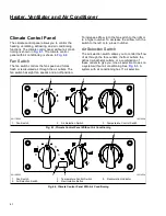
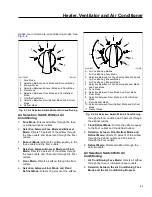
Page 66: ...he left or to a lower number Air Selection Switch The air selection switch allows you to control the flow of air through the face outlets the floor outlets the defrost windshield outlets or a combination of these outlets to give you nine air selection modes on a system without air conditioning See Fig 6 3 A system with air conditioning has 11 air selection 2 3 1 4 0 1 2 3 f831452a 06 17 2003 1 Fan S...

Page 67: ...e Directs all airflow through the defrost outlets Air Selection Switch With Air Conditioning 1 Air Conditioning Face Mode Directs all airflow through the face or instrument panel outlets 2 Selection between the Air Conditioning Face Mode and the Air Conditioning Bi Level 06 17 2003 1 2 3 4 5 6 7 8 9 f831455 1 Face Mode 2 Selection Between Face Mode and Bi Level Mode 3 Bi Level Mode 4 Selection Betwe...

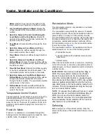
Page 68: ...ugh the heating and air conditioning system unless the recir culation mode if equipped is turned on Recirculation Mode The recirculation mode is only available on vehicles with air conditioning The recirculation mode limits the amount of outside air entering the cab Press the recirculation button to prevent dusty or smoky air from entering the cab The recirculation mode can also be used to decreas...

Page 69: ...r conditioning system has a brushless blower motor with a protection or shutdown mode to prevent damage due to overheating and overcurrent conditions If the brushless blower motor goes into a protection mode the motor will operate at a slower speed If the overheating or overcurrent condition con tinues the motor will shut down and stop com pletely The motor will resume proper operation after the m...

Page 70: ...ng 7 10 Starting After Extended Shutdown or Oil Change 7 10 Engine Break In 7 10 Engine Operation 7 10 Cruise Control 7 11 Power Takeoff PTO Governor 7 13 Cold Weather Operation 7 13 High Altitude Operation 7 13 Engine Shutdown 7 14 Engine Braking 7 14 Exhaust Braking Systems 7 15 ...

Page 71: ...ual for complete details and operation of the after treatment system Inside the ATD on Mercedes Benz Detroit Diesel and Cummins engines the exhaust first passes over the diesel oxidation catalyst DOC then it passes through the DPF which traps soot particles If ex haust temperature is high enough the trapped soot is reduced to ash in a process called passive regen eration regen Passive regeneration ...

Page 72: ...hicle shortly after an automatic regen ensure the exhaust outlets are directed away from struc tures trees vegetation flammable materials and anything else that may be damaged or injured by exposure to high heat A steady yellow DPF lamp indicates that a parked regen is required soon and should be scheduled for the earliest convenient time See Fig 7 2 A blinking yellow DPF lamp indicates that a par...

Page 73: ...ty may be compromised Use ultralow sulfur diesel with 15 ppm sulfur content or less Do not use fuel blended with used engine lube oil or kerosene Engine lube oil must have a sulfated ash level less than 1 0 wt currently referred to as CJ 4 oil Use only certified diesel exhaust fluid DEF in the DEF tank After exhaust gasses leave the engine they flow into the ATS First they flow into a two part ATD com...

Page 74: ... engine software not the driver A steadily illuminated HEST lamp alerts the operator of high exhaust temperatures when vehicle speed is below 5 mph 8 km h while it is performing an automatic regen and during a parked regen An illuminated DEF warning lamp in the gauge indicates that the DEF tank should be refilled at the next opportunity Parked Regen DANGER During parked regeneration exhaust tempera...

Page 75: ...n off the engine DPF Maintenance Eventually ash will accumulate in the DPF and the filter will require servicing DPF servicing must be performed by an authorized technician following the engine manufacturer s instructions A record must be maintained for warranty purposes that includes date of cleaning or replacement vehicle mileage particulate filter part number and serial number DEF DEF is used in ...

Page 76: ...h Level 1 Level 3 Level 2 Level 4 Filter Regeneration Recommended Filter is reaching Bring vehicle to highway speeds to Filter Regeneration Necessary Filter is now reaching maximum capacity To avoid engine derate bring vehicle Parked Regeneration Required Engine Derate Filter has reached maximum capacity Vehicle must be parked and a Parked Parked Regeneration Required Engine Shut Down Filter has e...

Page 77: ...ow the following warnings strongly encourage the driver to refill the DEF tank One bar of the DEF level indicator illuminates amber DEF very low refill DEF DEF warning lamp illuminates solid amber See Fig 7 11 The DEF tank must be filled to cancel the warning sequence DEF Empty When the DEF level reads empty the following warn ings are activated One bar of the DEF level indicator flashes red DEF empty...

Page 78: ...with progres sively harsher engine power limits applied If the fault is not corrected the STOP engine light illuminates and a 5 mph 8 km h speed limit will be applied after the next engine shut down or while parked and idling 11 08 2010 f611037 B 1 2 ULTRA LOW SULFUR DIESEL FUEL ONLY E F DEF F E 1 2 ULTRA LOW SULFUR DIESEL FUEL ONLY E F DEF F E 1 2 ULTRA LOW SULFUR DIESEL FUEL ONLY E F DEF F E A C...

Page 79: ...e the vehicle can cause the pinion to release and re engage which could cause ring gear and starter pinion damage Ring gear and starter pinion damage caused by improper starting procedures is not warrantable Pre Start NOTE These pre start steps apply to all en gines 1 Perform the engine pretrip inspection and daily maintenance checks in Chapter 11 2 Set the parking brake 3 For manual transmissions...

Page 80: ...ing protection at start up For this reason change the engine oil and filters after extended storage NOTICE Failure to eliminate water diluted lubricating oil may lead to serious engine damage at startup Before engine start up complete the engine pretrip and post trip inspections and maintenance proce dures in Chapter 11 Engine Break In Every engine is tested on a dynamometer before shipment elimina...

Page 81: ...d be enough to provide cab heat in above freezing ambient temperatures If the engine is programmed with the idle shutdown timer ninety seconds before the preset shutdown time the CHECK ENGINE light will begin to flash at a rapid rate If the position of the clutch pedal or ser vice brake changes during this final ninety seconds CHECK ENGINE lamp flashing the idle shutdown timer will be disabled until ...

Page 82: ... steps 1 1 Hold the accelerator pedal down until the speedometer reaches the desired speed 1 2 Push the SET button on the transmission shift knob 2 To disengage the cruise control do these steps 2 1 Press down the brake pedal on automatic and manual transmission or Press down the clutch pedal on manual transmission only 2 2 Push the PAUSE button on the transmis sion shift knob 3 To resume a presel...

Page 83: ... use in cold weather for your engine see the engine manu facturer s engine operation manual supplied in the vehicle documentation package If satisfactory engine temperature is not maintained maintenance costs will increase due to greater en gine wear If the engine coolant temperature be comes too low raw fuel will wash the lubricating oil off the cylinder walls and dilute the crankcase oil causing...

Page 84: ...brake switch controls the degree of en gine braking Normally there are two paddle switches a two position On Off Switch to activate the engine brake and a two position HI LO Switch to control the amount of engine braking To turn the two position On Off Switch on raise the paddle When the two position switch is on an amber LED light emitting diode illuminates inside the switch To turn the two posit...

Page 85: ... at the LO position when driving on flat open stretches of road If the service brakes are still required to slow down on a grade switch to a higher set ting on the dash switch until there is no need for the service brakes Grade descent speed should be such that the service brakes are used infrequently and that they remain cool thus retaining their effectiveness For maximum retarding maintain the to...

Page 86: ...ht on the switch illuminated an air cylinder shuts the but terfly valve which restricts the flow of exhaust gases and retards the engine This retarding action is car ried through the engine and drivetrain slowing the vehicle and reducing the need for frequent service brake applications Exhaust brakes are not intended for use as the pri mary braking system during vehicle operation Operating Character...

Page 87: ...cations are ad ditionally affected controlled or governed by engine speed through transmission gear selection The Alli son MD3060 transmission has automatic downshift ing when the exhaust brake is requested See the information on the Allison World Transmission later in this chapter On some applications when the Pacbrake is in use it may be necessary to check that the cruise control is not set and ...

Page 88: ...ed before shutting down the engine Allison World Transmission Pacbrake exhaust brakes on engines that are used with the Allison World Transmission MD series are interfaced with the transmission electronic control module ECM An exhaust brake enabled transmis sion ECM will usually provide converter lockup in gears two through six Effective exhaust braking be gins when the transmission automatically ...

Page 89: ... Fuller Straight Shift Transmissions 8 8 Eaton Fuller Range Shift Transmissions 8 9 Eaton Fuller AutoShift 8 12 Freightliner SmartShift Shift Control 8 15 Eaton Fuller UltraShift 8 15 Mercedes Benz Manual Transmissions 8 22 Mercedes Benz Automated Transmissions 8 22 Meritor Drive Axles 8 26 ...

Page 90: ...le on an Incline With a Slipping Clutch A slipping clutch accumulates heat faster than it can be dissipated resulting in early clutch failures Never use the clutch to hold a vehicle on a hill Coasting With the Clutch Released pedal down and the Transmission in Gear WARNING Do not coast with the clutch released pedal de pressed and the transmission in gear High driven disc rpm could cause the clutc...

Page 91: ...he applicable section in Group 25 of the Business Class M2 Workshop Manual for clutch adjustment procedures and specifications CAUTION Operating the vehicle with the clutch incorrectly adjusted could result in clutch or clutch brake failure Clutch Lubrication The release bearing should be lubricated at frequent intervals See Group 25 of the Business Class M2 Maintenance Manual for intervals and pro...

Page 92: ...ecessary to keep the vehicle from moving 2000 Series On vehicles with Allison 2000 series transmissions do the following steps if you have to leave the cab with the engine running for example when checking the transmission fluid Without Auto Apply Parking Brake Follow the instructions for vehicles with 1000 series transmissions under the heading Without Park Posi tion With Auto Apply Parking Brake ...

Page 93: ...d range to reverse or from reverse to a forward range CAUTION Extended idling in reverse may cause transmis sion overheating and damage Do not idle in reverse for more than 5 minutes Se lect P park PB auto apply parking brake or N neutral when time at idle exceeds 5 minutes NOTE The shift into reverse may not succeed if a range inhibitor is active Check for illumination of the RANGE INHIBIT indica...

Page 94: ...NOTE To have the transmission select these ranges automatically leave the selector lever in D drive Allison MD Series Refer to the Allison website for additional information www allisontransmission com Safety Precautions WARNING Do not leave the vehicle unattended with the en gine running If you leave the vehicle and the en gine is running the vehicle can move suddenly which could result in person...

Page 95: ...l at start up WARNING Failure to apply the vehicle parking brakes when the transmission is in neutral may allow the ve hicle to move unexpectedly possibly causing property damage or personal injury When neutral is selected the vehicle service brakes parking brake or emergency brake must be applied Selecting neutral does not apply vehicle brakes un less an auxiliary system to apply the parking brak...

Page 96: ...in control The transmission has a feature to prevent automatic upshifting above the lower range selected However during downhill operation if the engine governed speed is exceeded in the lower range the transmission may upshift to the next higher range 1 First Range Use the first range when pulling through mud or deep snow when maneuvering in tight spaces or when driving up or down steep grades Fir...

Page 97: ...at one time If the mode indicator LED is illuminated the displayed code is active If it is not illuminated the displayed code is not active NOTE During normal operation an illuminated mode indicator LED signifies the specialized mode operation is in use To enter diagnostics mode first park the vehicle and apply the parking brake Then simultaneously press both the up and down arrows twice Eaton Fulle...

Page 98: ...the shift lever to neutral Engage the clutch again With the shift lever in neutral disengage the clutch and move the shift lever to the next lowest gear 4 3 Engage the clutch smoothly 4 4 Use the sequence described above to shift progressively down through each successive lower gear as driving condi tions require Eaton Fuller Range Shift Transmissions Refer to the Eaton website for additional info...

Reviews: