SINGLE SCREW CHILLERS IMM
46
Engineered for Flexibility and Performance
5. Switch Adjustment
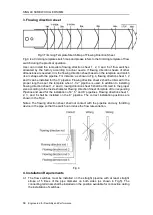
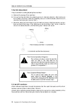
The procedures for setting adjusting flow switches:
A. Remove the casing of flow switches:
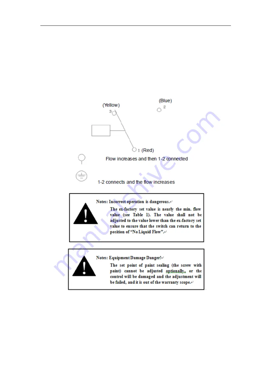
B. Turn up the flow and rotate the adjusting screw in clockwise direction. After turning up
the ex-factory set value, rotate the adjusting screw in counterclockwise director to turn
down the flow value (as shown in Fig.1).
C. Press the driving lever for times to ensure that the set value of the flow switch is no less
than ex-nfactory set value. If the driving lever returns without “click” sound, rotate the
screw in clockwise direction until the driving lever makes such sound.
6. Check Procedures
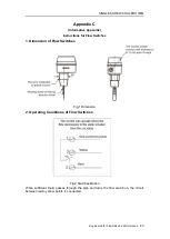
When sufficient liquid flows through the pipeline, the flow switch actuates and the circuit
between red and yellow contact points connects.
At least three operating periods shall be observed to ensure the normal operation of the
flow switches and the connected system before the installation is complete.


