


SiUS331604E
Outline of Control (Indoor Unit)
Functions and Control
64
6.9
Freeze-up Prevention
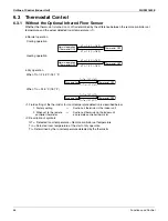
Freeze-up Prevention by Off Cycle (Indoor Unit Individual Control)
When the temperature detected by the liquid pipe temperature thermistor of the indoor heat exchanger drops too
low, the unit enters freeze-up prevention control in accordance with the following conditions, and is also set in
accordance with the conditions given below. (Thermostat OFF)
When freeze-up prevention is activated, the electronic expansion valve is closed, the drain pump turns on and
the airflow rate is fixed to L tap. When the following conditions for cancelling are satisfied, it will reset.
Conditions for starting:
Liquid pipe temperature
≤
– 1°C (30.2°F) (for total of 40 minutes)
or
Liquid pipe temperature
≤
– 5°C (23°F) (for total of 10 minutes)
Condition for cancelling:
Liquid pipe temperature
≥
+7°C (44.6°F) (for 10 minutes continuously)
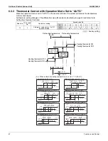
The idea of freeze-up prevention control
Difficult to carry out freeze-up prevention operation
· For comfort, suppression of frequent thermostat ON/OFF is necessary.
· Suppressing the switching frequency of the compressor is required to ensure reliability.
After freeze-up prevention operation is carried out, the compressor can be defrosted properly.
· Water leakage prevention must be effective.
Normal operation
Start
Cancel
Liquid pipe
temperature
Start
Cancel
Normal operation
–
5
ºC
(23˚F)
0
ºC
(32˚F)
+
7
ºC
(44.6˚F)
–
1
ºC
(30.2˚F)
t1
t2
t3
t4
0
ºC
(32˚F)
+
7
ºC
(44.6˚F)
10 min.
OR
10 min.
10 min.
t
>
40
minutes
Freeze-up prevention control
Forced OFF by thermostat
Freeze-up prevention control
Forced OFF by thermostat
Summary of Contents for VRV IV-S RXTQ-TAVJU Series
Page 1: ...Service Manual SiUS331604E RXTQ36 48 60TAVJU Heat Pump 60 Hz...
Page 254: ...Wiring Diagrams SiUS331604E 241 Appendix RXTQ48TAVJU 3D100496A...
Page 255: ...SiUS331604E Wiring Diagrams Appendix 242 RXTQ60TAVJU 3D100497A...
Page 260: ...Wiring Diagrams SiUS331604E 247 Appendix FXEQ07 09 12 15 18 24PVJU C 3D098557...
Page 267: ...SiUS331604E Wiring Diagrams Appendix 254 FXTQ12 18 24 30 36 42 48 54PAVJU 3D065036G...
Page 270: ...Wiring Diagrams SiUS331604E 257 Appendix VAM1200GVJU 3D073270C...
Page 271: ...Revision History Month Year Version Revised contents 06 2016 SiUS331604E First edition...


