16 Configuration
Installation and operation manual
30
RK RKXYQ8T7Y1B
VRV IV compressor unit for indoor installation
4P499900-1A – 2020.10
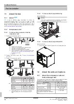
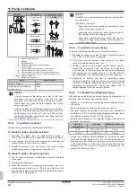
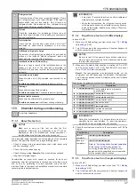
5 HP
BS2
SET
BS1
MODE
BS3
RETURN
BS4
TEST
BS5
RESET
H1P
H2P
H3P
H4P
H5P
H6P
H7P
H8P
1 2
OFF
ON
DS1
1 2 3 4
OFF
ON
DS1
1 2 3 4
OFF
ON
DS2
MULTI
DEMAND
L.N.O.P.
SLAVE
MASTER
IND
TEST/
HWL
MODE
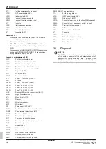
8 HP
A1P
BS1 BS2 BS3
A1P
ON (
) OFF ( ) Flashing (
)
ON (
) OFF (
) Flashing (
)
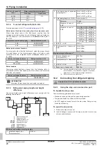
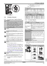
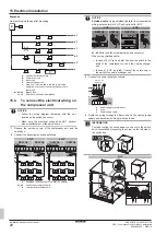
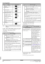
DIP switches
Only change the factory settings if you install a cool/heat selector
switch.
Model
DIP switch
5 HP
▪ DS1‑1: COOL/HEAT selector (refer to the
manual of the cool/heat selector switch).
OFF=not installed=factory setting
▪ DS1‑2: NOT USED. DO NOT CHANGE THE
FACTORY SETTING.
8 HP
▪ DS1‑1: COOL/HEAT selector (see
options for the compressor unit and heat
exchanger
OFF=not
installed=factory setting
▪ DS1‑2~4: NOT USED. DO NOT CHANGE THE
FACTORY SETTING.
▪ DS2‑1~4: NOT USED. DO NOT CHANGE THE
FACTORY SETTING.
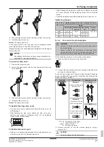
Push buttons
Use the push buttons to make the field settings. Operate the push
buttons with an insulated stick (such as a closed ball-point pen) to
avoid touching of live parts.
The push buttons differ depending on the model.
Model
Push buttons
5 HP
▪ BS1: MODE: For changing the set mode
▪ BS2: SET: For field setting
▪ BS3: RETURN: For field setting
▪ BS4: TEST: For test operation
▪ BS5: RESET: For resetting the address when
the wiring is changed or when an additional
indoor unit is installed
8 HP
▪ BS1: MODE: For changing the set mode
▪ BS2: SET: For field setting
▪ BS3: RETURN: For field setting
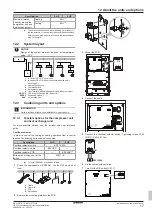
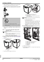
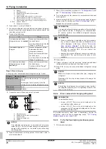
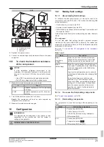
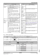
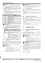
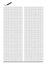
7‑LEDs display or 7-segments display
The display gives feedback about the field settings, which are
defined as [Mode-Setting]=Value.
The display differs depending on the model.
Model
Display
5 HP
7‑LEDs display:
▪ H1P: Shows the mode
▪ H2P~H7P: Shows the settings and values,
represented in binary code
(H8P: NOT used for field settings, but used during
initialisation)
8 HP
7‑segments display (
)
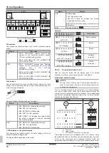
Example:
H1P H2P H3P H4P H5P H6P H7P
-
+
+
+
+
+
[
H1P
32 16
8
4
2
1]
Description
(H1P OFF)
Default situation
(H1P flashing)
Mode 1
(H1P ON)
Mode 2
+
+
+
+
+
0
0
8
0
0
0
(H2P~H7P = binary 8)
Setting 8
(in mode 2)
+
+
+
+
+
0
0
0
4
0
0
(H2P~H7P = binary 4)
Value 4
(in mode 2)
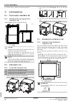
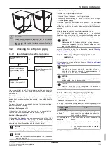
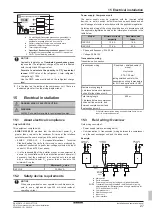
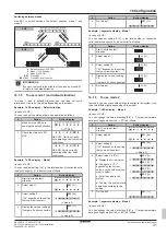
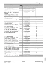
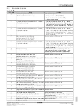
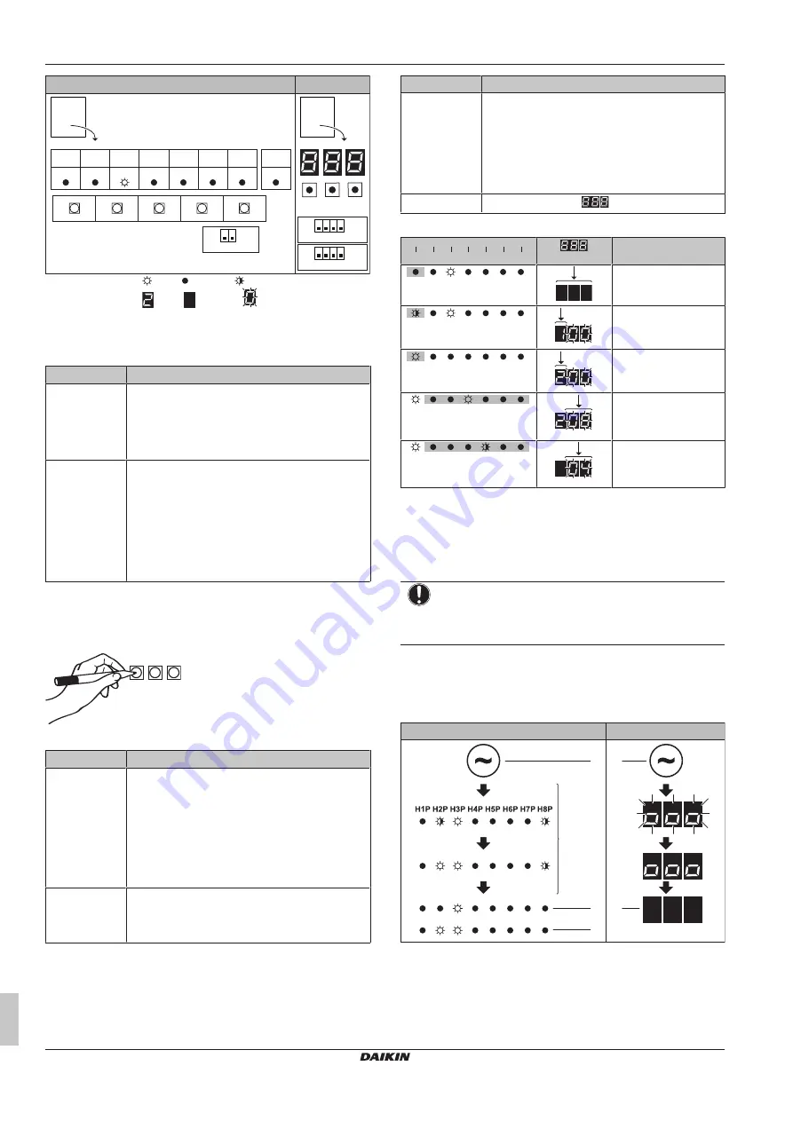
16.1.4
To access mode 1 or 2
After the units are turned ON, the display goes to its default
situation. From there, you can access mode 1 and mode 2.
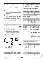
Initialisation: default situation
NOTICE
Be sure to turn ON the power 6 hours before operation in
order to have power running to the crankcase heater and
to protect the compressor.
Turn on the power supply of the compressor unit, heat exchanger
unit, and all indoor units. When the communication between the
compressor unit, heat exchanger unit, and indoor units is established
and normal, the display indication state will be as below (default
situation when shipped from factory).
1~2 min
8~10 min
10~12 min
5 HP
8 HP
b
c
b
a
a
a
Power ON
b
Default situation
c
LED indication when there is a malfunction
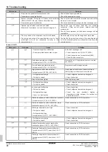
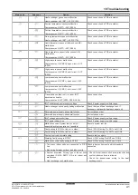
If the default situation is not displayed after 10~12 minutes, check
the malfunction code on the indoor unit user interface (and in case of
8 HP on the compressor unit 7‑segment display). Solve the
malfunction code accordingly. First, check the communication wiring.


