


Troubleshooting by Indication on the Remote Controller
Si34-601A
264
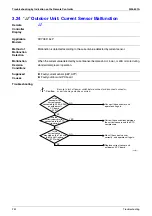
Troubleshooting
3.34
“
L8
”
Outdoor Unit:
Inverter Current Abnormal
Remote
Controller
Display
L8
Applicable
Models
RXYQ5P~54P
Method of
Malfunction
Detection
Malfunction is detected by current flowing in the power transistor.
Malfunction
Decision
Conditions
When overload in the compressor is detected. (Inverter secondary current 16.1A)
Supposed
Causes
Compressor overload
Compressor coil disconnected
Defect of inverter PC board
Faulty compressor
Troubleshooting
Output current check
Caution
Be sure to turn off power switch before connect or disconnect connector,
or parts damage may be occurred.
Power ON
Power OFF
NO
NO
NO
NO
NO
YES
YES
YES
YES
NO
YES
NO
A current
of not less than 15A
flows through the
compressor.
Are wire
connections properly
made (according to the
Wiring Diagram)?
The insulation
resistance is low, i.e.,
not more than
100k
Ω
.)
Does the
power transistor have any
abnormalities?
Is the stop valve
open?
Disconnect the cable from the
compressor, and then check
the compressor for the
insulation resistance.
Check the power transistor on
the inverter PC board using a
multiple tester.
Connect the compressor cable,
and then restart the operation.
Check the compressor cable for
any disconnection or flaws.
Overcurrent:
Check the compressor
and refrigerant system
(in the same manner as
that for E3).
Open the stop valve.
Rectify the wire
connetions.
Replace the
compressor.
Replace the inverter
PCB.
The inverter is likely to
have got faulty due to
the malfunction of the
compressor.
After the completion of
replacement, be sure
to check the
compresssor.
A
Summary of Contents for VRV III RXYQ5-54PY1
Page 1: ...RXYQ5 54PY1 R 410A Heat Pump 50Hz Si34 601A...
Page 101: ...Refrigerant Flow for Each Operation Mode Si34 601A 90 Refirgerant Circuit...
Page 153: ...Outline of Control Indoor Unit Si34 601A 142 Function...
Page 219: ...Troubleshooting by Remote Controller Si34 601A 208 Troubleshooting...
Page 226: ...Si34 601A Troubleshooting by Remote Controller Troubleshooting 215...
Page 325: ...Troubleshooting OP Unified ON OFF Controller Si34 601A 314 Troubleshooting...
Page 327: ...Piping Diagrams Si34 601A 316 Appendix 1 Piping Diagrams 1 1 Outdoor Unit RXYQ5PY1 3D050782...
Page 328: ...Si34 601A Piping Diagrams Appendix 317 RXYQ8P 3D050783...
Page 329: ...Piping Diagrams Si34 601A 318 Appendix RXYQ10P 12PY1 3D050784...
Page 330: ...Si34 601A Piping Diagrams Appendix 319 RXYQ14P 16P 18PY1 3D050785...
Page 336: ...Si34 601A Wiring Diagrams for Reference Appendix 325 RXYQ8PY1 3D050454J...
Page 337: ...Wiring Diagrams for Reference Si34 601A 326 Appendix RXYQ10PY1 3D050455H...
Page 338: ...Si34 601A Wiring Diagrams for Reference Appendix 327 RXYQ12PY1 3D051890G...
Page 339: ...Wiring Diagrams for Reference Si34 601A 328 Appendix RXYQ14P 16P 18PY1 3D050456H...
Page 344: ...Si34 601A Wiring Diagrams for Reference Appendix 333 FXCQ40M 50M 80M 125MVE 3D039557A...
Page 346: ...Si34 601A Wiring Diagrams for Reference Appendix 335 FXZQ20M 25M 32M 40M 50M7V1B 3D038359...
Page 347: ...Wiring Diagrams for Reference Si34 601A 336 Appendix FXKQ25MA 32MA 40MA 63MAVE 3D039564C...
Page 352: ...Si34 601A Wiring Diagrams for Reference Appendix 341 FXMQ200MA 250MAVE 3D039621B...
Page 353: ...Wiring Diagrams for Reference Si34 601A 342 Appendix FXHQ32MA 63MA 100MAVE 3D039801D...
Page 356: ...Si34 601A Wiring Diagrams for Reference Appendix 345 FXUQ71MA 100MA 125MAV1 3D044973A...
Page 357: ...Wiring Diagrams for Reference Si34 601A 346 Appendix FXMQ125MF 200MF 250MFV1 3D044996C...
Page 358: ...Si34 601A Wiring Diagrams for Reference Appendix 347 BEVQ71MA 100MA 125MAVE 3D044901B...
Page 381: ...Method of Checking The Inverter s Power Transistors and Diode Modules Si34 601A 370 Appendix...
Page 395: ...Si34 601A iv Index...