


Basic Control
Si39-502A
58
Function
2.3
Electronic Expansion Valve PI Control
Main Motorized Valve EV1 Control
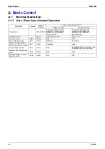
Carries out the motorized valve (Y1E) PI control to maintain the evaporator outlet superheated
degree (SH) at constant during heating operation to make maximum use of the outdoor unit
heat exchanger (evaporator).
The optimum initial value of the evaporator outlet superheated degree is 5°C, but varies
depending on the discharge pipe superheated degree of inverter compressor.
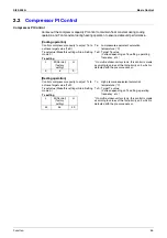
Subcooling Motorized Valve EV2 Control
Makes PI control of the motorized valve (Y2E) to keep the superheated degree of the outlet gas
pipe on the evaporator side for the full use of the subcooling heat exchanger.
2.4
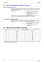
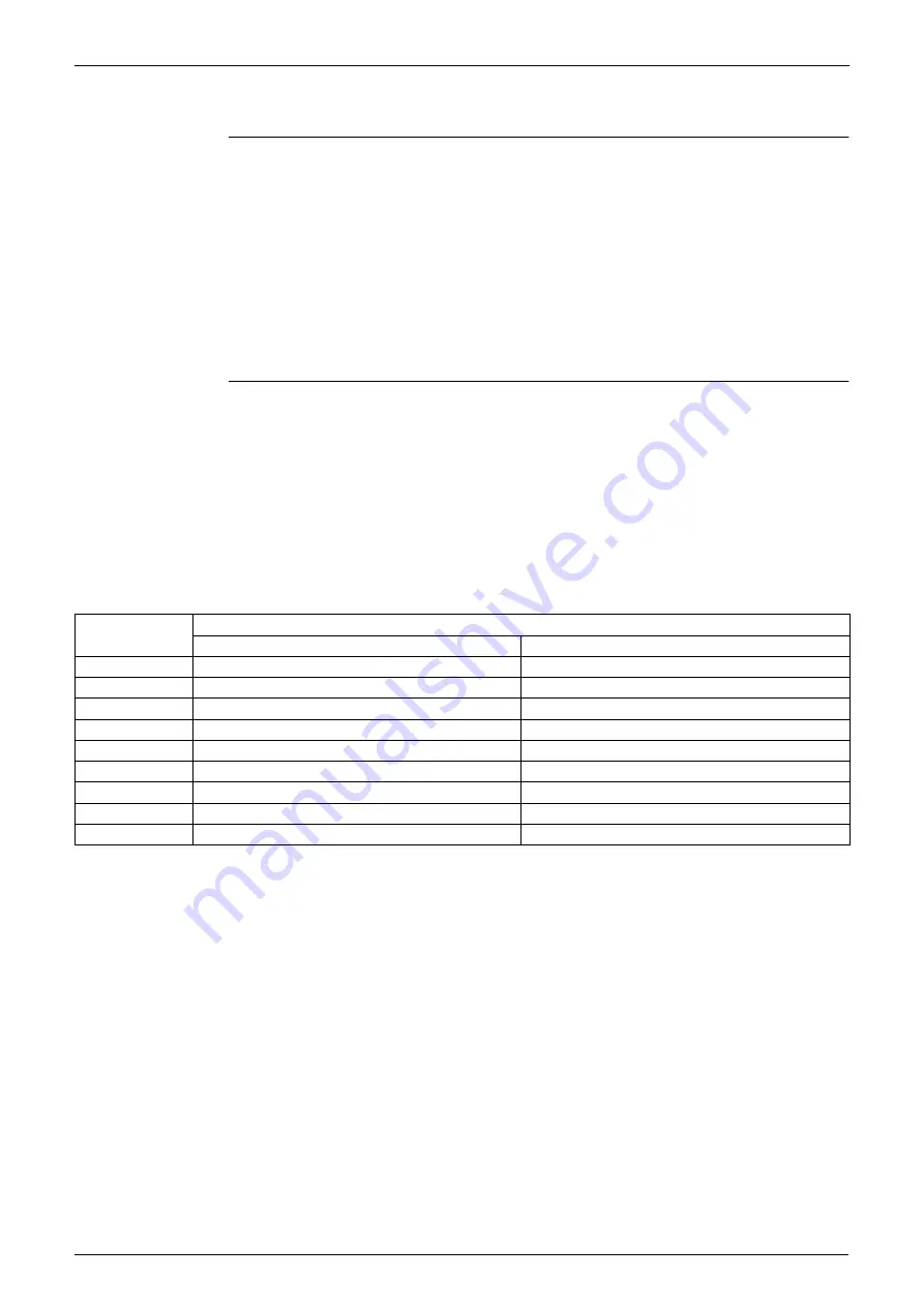
Step Control of Outdoor Unit Fans
Used to control the revolutions of outdoor unit fans in the steps listed in table below, according to condition changes.
∗
Figures listed above are all those controlled while in standard mode, which vary when the system is set to high static
pressure or capacity precedence mode.
SH = Ts - Te
SH : Evaporator outlet superheated degree (°C)
Ts : Suction pipe temperature detected by
thermistor R2T (°C)
Te : Low pressure equivalent saturation
temperature (°C)
SH = Tsh
-Te
SH : Outlet superheated degree of evaporator (
°
C)
Tsh : Suction pipe temperature detected with the
thermistor R5T (
°
C)
Te : Low pressure equivalent saturation
temperature (
°
C)
STEP
No.
Fan revolutions (rpm)
RXYQ8M
RXYQ10M
0
0
0
1
300
300
2
320
320
3
345
345
4
385
385
5
465
465
6
575
575
7
765
785
8
825
825
Summary of Contents for VRV II RXYQ8MY1K
Page 53: ...Specifications Si39 502A 42 Specifications...
Page 143: ...Field Setting Si39 502A 132 Test Operation...
Page 258: ...Si39 502A Wiring Diagrams for Reference Appendix 247 FXCQ40M 50M 80M 125MVE 3D039557A...
Page 260: ...Si39 502A Wiring Diagrams for Reference Appendix 249 FXKQ25M 32M 40M 63MVE 3D039564A...
Page 264: ...Si39 502A Wiring Diagrams for Reference Appendix 253 FXMQ40M 50M 63M 80M 100M 125MVE 3D039620A...
Page 265: ...Wiring Diagrams for Reference Si39 502A 254 Appendix FXMQ200M 250MVE 3D039621A...
Page 266: ...Si39 502A Wiring Diagrams for Reference Appendix 255 FXHQ32M 63M 100MVE 3D039801C...
Page 267: ...Wiring Diagrams for Reference Si39 502A 256 Appendix FXAQ20M 25M 32M 40M 50M 63MVE 3D034206A...
Page 269: ...Wiring Diagrams for Reference Si39 502A 258 Appendix FXUQ71M 100M 125MV1 3D044973...
Page 270: ...Si39 502A Wiring Diagrams for Reference Appendix 259 FXAQ20MH 25MH 32MH 40MH 50MHV1 3D046348A...
Page 271: ...Wiring Diagrams for Reference Si39 502A 260 Appendix FXLQ20MH 25MH 32MH 40MH 50MHV1 3D046787A...
Page 272: ...Si39 502A Wiring Diagrams for Reference Appendix 261 BEVQ50MVE 3D046579A Notes...
Page 273: ...Wiring Diagrams for Reference Si39 502A 262 Appendix BEVQ71M 100M 125MVE 3D044901A Notes...
Page 285: ...Piping Installation Point Si39 502A 274 Appendix...
Page 293: ...Method of Replacing The Inverter s Power Transistors and Diode Modules Si39 502A 282 Appendix...
Page 307: ...Si39 502A iv Index...


