


Functional Parts Layout
Si39-502A
46
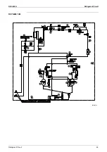
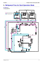
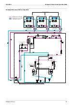
Refirgerant Circuit
2.
Functional Parts Layout
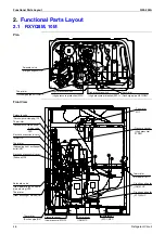
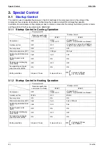
2.1
RXYQ8M, 10M
Plan
Front View
Solenoid valve
(Hot gas bypass)Y1S
Thermistor
(Discharge pipe M1C)R31T
Thermistor
(Discharge pipe M2C)R32T
High pressure switch
(High pressure protection)S1PH
High pressure switch
(High pressure protection)S2PH
Fan motor
M1F
Pressure sensor
(High pressure)
S1NPH
Thermistor
(Outdoor air)R1T
Compressor
(INV)M1C
Compressor
(STD1)M2C
Thermistor
(Suction pipe)R2T
Pressure sensor
(Low pressure)S1NPL
Thermistor
(Subcooling heat exchanger
outlet)R5T
Thermistor
(Heat exchanger cleicen)R4T
Solenoid valve
(Non-operating unit liquid
pipe closing)Y3S
Electronic expansion valve coil
(Subcool)Y2E
Electronic expansion valve coil
(Main)Y1E
4-way valve
Y4S
Thermistor
(Receiver outlet liquid pipe)R6T
Solenoid valve
(Receiver gas discharging)Y2S
Crank case heater
(INV)E1HC
Crank case heater
(STD)E2HC
Summary of Contents for VRV II RXYQ8MY1K
Page 53: ...Specifications Si39 502A 42 Specifications...
Page 143: ...Field Setting Si39 502A 132 Test Operation...
Page 258: ...Si39 502A Wiring Diagrams for Reference Appendix 247 FXCQ40M 50M 80M 125MVE 3D039557A...
Page 260: ...Si39 502A Wiring Diagrams for Reference Appendix 249 FXKQ25M 32M 40M 63MVE 3D039564A...
Page 264: ...Si39 502A Wiring Diagrams for Reference Appendix 253 FXMQ40M 50M 63M 80M 100M 125MVE 3D039620A...
Page 265: ...Wiring Diagrams for Reference Si39 502A 254 Appendix FXMQ200M 250MVE 3D039621A...
Page 266: ...Si39 502A Wiring Diagrams for Reference Appendix 255 FXHQ32M 63M 100MVE 3D039801C...
Page 267: ...Wiring Diagrams for Reference Si39 502A 256 Appendix FXAQ20M 25M 32M 40M 50M 63MVE 3D034206A...
Page 269: ...Wiring Diagrams for Reference Si39 502A 258 Appendix FXUQ71M 100M 125MV1 3D044973...
Page 270: ...Si39 502A Wiring Diagrams for Reference Appendix 259 FXAQ20MH 25MH 32MH 40MH 50MHV1 3D046348A...
Page 271: ...Wiring Diagrams for Reference Si39 502A 260 Appendix FXLQ20MH 25MH 32MH 40MH 50MHV1 3D046787A...
Page 272: ...Si39 502A Wiring Diagrams for Reference Appendix 261 BEVQ50MVE 3D046579A Notes...
Page 273: ...Wiring Diagrams for Reference Si39 502A 262 Appendix BEVQ71M 100M 125MVE 3D044901A Notes...
Page 285: ...Piping Installation Point Si39 502A 274 Appendix...
Page 293: ...Method of Replacing The Inverter s Power Transistors and Diode Modules Si39 502A 282 Appendix...
Page 307: ...Si39 502A iv Index...


