


Troubleshooting by Indication on the Remote Controller
Si39-502A
194
Troubleshooting
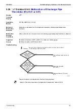
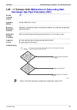
3.37
“
P1
”
Outdoor Unit:
Inverter Over-Ripple Protection
Remote
Controller
Display
P1
Applicable
Models
RXYQ8~30MY1K (E), YLK (E)
Method of
Malfunction
Detection
Imbalance in supply voltage is detected in PC board.
Malfunction
Decision
Conditions
When the resistance value of thermistor becomes a value equivalent to open or short circuited
status.
Malfunction is not decided while the unit operation is continued.
"P1" will be displayed by pressing the inspection button.
Supposed
Causes
Open phase
Voltage imbalance between phases
Defect of main circuit capacitor
Defect of inverter PC board
Defect of K1M
Improper main circuit wiring
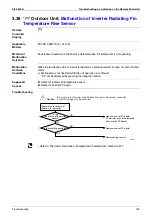
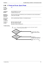
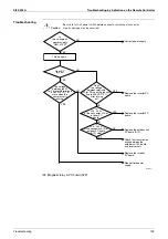
Troubleshooting
(V2816)
Caution
Be sure to turn off power switch before connect or disconnect connector,
or parts damage may be occurred.
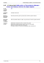
Is
the voltage
imbalance applied to the
inverter in excess of
14 V (Y1)?
∗
2
NO
Part or wiring defect
After turning the power supply
OFF, check and repair the
main circuit wiring or parts.
(1) Loose or disconnected
wiring between power
supply and inverter
(2) K1M contact disposition,
fusion or contact is poor.
(3) Loose or disconnected
noise filter
Using a device capable of
constant recording of power
supply voltage record
power supply voltage
between 3 phases (L1 ~ L2,
L2 ~ L3, L3~L1) for about
one continuous week.
Open phase
Normalize field cause.
Power supply voltage imbalance
Explanation for users
Fix power supply voltage
imbalance.
YES
YES
NO
Imbalance
in supplied voltage is
in excess of 14 V
(Y1).
∗
1
Open phase?
<When voltage monitoring is possible:>
∗
1. Measure voltage at the X1M power supply
terminal block.
∗
2. Measure voltage at terminals L1, L2 and L3 of
the diode module inside the inverter while the
compressor is running.
∗
In accordance with "notification of inspection results" accompanying spare parts.
Give the user a copy of "notification of inspection results"and leave
it up to him to improve the imbalance.
Be sure to explain to the user that
there is a "power supply imbalance"
for which DAIKIN is not responsible.
measure
YES
NO
Summary of Contents for VRV II RXYQ8MY1K
Page 53: ...Specifications Si39 502A 42 Specifications...
Page 143: ...Field Setting Si39 502A 132 Test Operation...
Page 258: ...Si39 502A Wiring Diagrams for Reference Appendix 247 FXCQ40M 50M 80M 125MVE 3D039557A...
Page 260: ...Si39 502A Wiring Diagrams for Reference Appendix 249 FXKQ25M 32M 40M 63MVE 3D039564A...
Page 264: ...Si39 502A Wiring Diagrams for Reference Appendix 253 FXMQ40M 50M 63M 80M 100M 125MVE 3D039620A...
Page 265: ...Wiring Diagrams for Reference Si39 502A 254 Appendix FXMQ200M 250MVE 3D039621A...
Page 266: ...Si39 502A Wiring Diagrams for Reference Appendix 255 FXHQ32M 63M 100MVE 3D039801C...
Page 267: ...Wiring Diagrams for Reference Si39 502A 256 Appendix FXAQ20M 25M 32M 40M 50M 63MVE 3D034206A...
Page 269: ...Wiring Diagrams for Reference Si39 502A 258 Appendix FXUQ71M 100M 125MV1 3D044973...
Page 270: ...Si39 502A Wiring Diagrams for Reference Appendix 259 FXAQ20MH 25MH 32MH 40MH 50MHV1 3D046348A...
Page 271: ...Wiring Diagrams for Reference Si39 502A 260 Appendix FXLQ20MH 25MH 32MH 40MH 50MHV1 3D046787A...
Page 272: ...Si39 502A Wiring Diagrams for Reference Appendix 261 BEVQ50MVE 3D046579A Notes...
Page 273: ...Wiring Diagrams for Reference Si39 502A 262 Appendix BEVQ71M 100M 125MVE 3D044901A Notes...
Page 285: ...Piping Installation Point Si39 502A 274 Appendix...
Page 293: ...Method of Replacing The Inverter s Power Transistors and Diode Modules Si39 502A 282 Appendix...
Page 307: ...Si39 502A iv Index...


