


Si39-502A
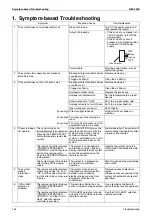
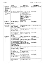
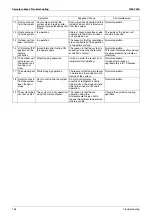
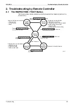
Troubleshooting by Remote Controller
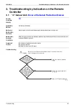
Troubleshooting
143
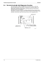
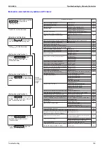
2.4
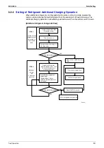
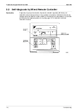
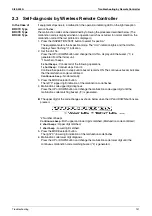
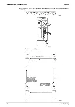
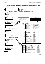
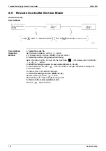
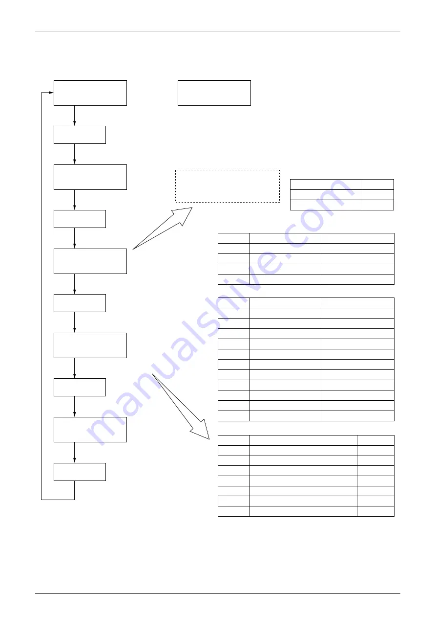
Operation of The Remote Controller’s Inspection / Test
Operation Button
Inspection/test
operation
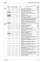
Example model
FXCQ25
FXFQ63
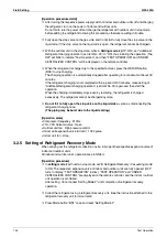
Example of capacity code display
Display
028
071
Product classification
VRV system
VRV system
VRV system
VRV system
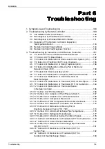
Display
1
2
F
H
Indoor unit system code
System classification
(VAV indoor unit)
Outdoor air processing unit
Standard indoor unit
New ceilling suspended cassette
Indoor unit type code
Type
VRV System Inverter K Series
R-407C VRV PLUS Series
VRV Heat Recovery Series
High COP type R-407C L Series
VRV II
VRV II M/C
VRV II High Outdoor Temperature Use
Display
A A 1
A A 3
A 9 2
A A 5
A A A
A A C
A 6 C
Outdoor model code
Model
RSXYP
RXYP
RSEYP
RSXYP-L
RXYQ-M
RXYQ-MA
RXYQ-M
Unit
Malfunction code
Inspection
Normal display (No display)
0
L 0
Malfunction code blinks when a malfunction occurs.
Unit
Malfunction code
Inspection
Inspection mode
Push the button.
Inspection/test
operation
Push the button.
Inspection/test
operation
Push the button.
Inspection/test
operation
Push the button.
Inspection/test
operation
Push the button.
0
L 0
Indoor unit model code display
0 7 1
F C J
Outdoor unit model code display
– – –
A 6 C
Test operation
Test operation mode
Capacity code
Indoor unit system code
Indoor unit type code
Progression code
0 7 1...
F...
C...
J...
(V2775)
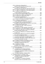
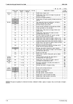
Type
Wall mounted
Double flow
Corner
Multi flow
Ceiling suspended
Built-in
Floor standing
Concealed ceiling duct
Concealed floor standing type
Slim Ceilling mounted duct
New ceilling suspended cassette
Display
A
C
E
F
H
J
L
P
L
3
5
Model
FXAQ
FXCQ
FXKQ
FXFQ
FXHQ
FXSQ
FXLQ
FXMQ
FXNQ
FXDQ
FXUQ
Summary of Contents for VRV II RXYQ8MY1K
Page 53: ...Specifications Si39 502A 42 Specifications...
Page 143: ...Field Setting Si39 502A 132 Test Operation...
Page 258: ...Si39 502A Wiring Diagrams for Reference Appendix 247 FXCQ40M 50M 80M 125MVE 3D039557A...
Page 260: ...Si39 502A Wiring Diagrams for Reference Appendix 249 FXKQ25M 32M 40M 63MVE 3D039564A...
Page 264: ...Si39 502A Wiring Diagrams for Reference Appendix 253 FXMQ40M 50M 63M 80M 100M 125MVE 3D039620A...
Page 265: ...Wiring Diagrams for Reference Si39 502A 254 Appendix FXMQ200M 250MVE 3D039621A...
Page 266: ...Si39 502A Wiring Diagrams for Reference Appendix 255 FXHQ32M 63M 100MVE 3D039801C...
Page 267: ...Wiring Diagrams for Reference Si39 502A 256 Appendix FXAQ20M 25M 32M 40M 50M 63MVE 3D034206A...
Page 269: ...Wiring Diagrams for Reference Si39 502A 258 Appendix FXUQ71M 100M 125MV1 3D044973...
Page 270: ...Si39 502A Wiring Diagrams for Reference Appendix 259 FXAQ20MH 25MH 32MH 40MH 50MHV1 3D046348A...
Page 271: ...Wiring Diagrams for Reference Si39 502A 260 Appendix FXLQ20MH 25MH 32MH 40MH 50MHV1 3D046787A...
Page 272: ...Si39 502A Wiring Diagrams for Reference Appendix 261 BEVQ50MVE 3D046579A Notes...
Page 273: ...Wiring Diagrams for Reference Si39 502A 262 Appendix BEVQ71M 100M 125MVE 3D044901A Notes...
Page 285: ...Piping Installation Point Si39 502A 274 Appendix...
Page 293: ...Method of Replacing The Inverter s Power Transistors and Diode Modules Si39 502A 282 Appendix...
Page 307: ...Si39 502A iv Index...


