


Field Setting
Si39-504
120
Test Operation
3.1.7
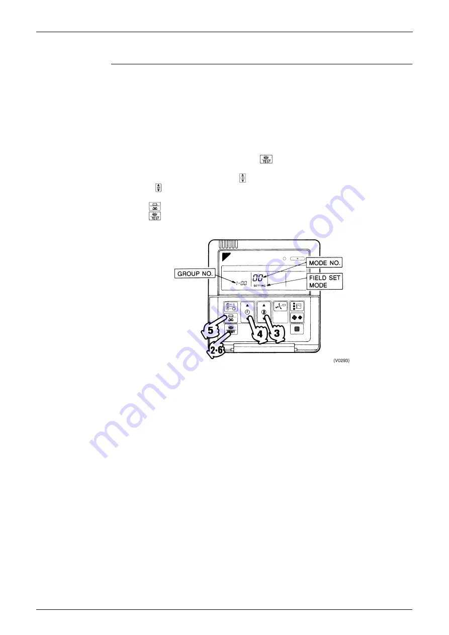
Centralized Control Group No. Setting
BRC1A Type
Set the group number of each group of the indoor unit from the remote controller. (In case of no
remote controller, also connect the remote controller and set the group No. Then, remove the
remote controller.)
1. Turn ON the power of the indoor unit and central remote controller.
(Unless the power is ON, no setting can be made.)
Check that the installation and electrical wiring are correct before turning the power supply
ON.
(When the power supply is turned ON, all LCD appear once and the unit may not accept the
operation for about one minute with the display of “
88
”.)
2. While in the normal mode, hold down the “
” button for a minimum of 4 seconds.
The remote controller will enter the FIELD SET MODE.
3. Select the MODE No. “
00
” with the “
” button.
4. Use the “
” button to select the group No. for each group.
5. (Group numbers increase in the order of 1-00, 1-01, ... 1-15, 2-00, ... 4-15.)
6. Press “
” to set the selected group No.
7. Press “
” to return to the NORMAL MODE.
Note:
For wireless remote controller, see the following.
For setting group No. of HRV and wiring adaptor for other air conditioners, etc., refer to the
instruction manual attached.
NOTICE
Enter the group No. and installation place of the indoor unit into the attached installation table.
Be sure to keep the installation table with the operation manual for maintenance.
Summary of Contents for VRV II RXYQ5MATL
Page 53: ...Specifications Si39 504 42 Specifications...
Page 115: ...Outline of Control Indoor Unit Si39 504 104 Function...
Page 161: ...Field Setting Si39 504 150 Test Operation...
Page 172: ...Si39 504 Troubleshooting by Remote Controller Troubleshooting 161...
Page 266: ...Si39 504 Piping Diagrams Appendix 255 RXYQ8MA 10MA 12MAYL E TL E 3D048033A...
Page 267: ...Piping Diagrams Si39 504 256 Appendix RXYQ14MA 16MAYL E TL E 3D048034A...
Page 271: ...Wiring Diagrams for Reference Si39 504 260 Appendix RXYQ8MA 10MA 12MAYL E 3D047088C...
Page 272: ...Si39 504 Wiring Diagrams for Reference Appendix 261 RXYQ14MA 16MAYL E 3D047089C...
Page 273: ...Wiring Diagrams for Reference Si39 504 262 Appendix 2 1 2 RXYQ MATL E RXYQ5MATL E 3D049059A...
Page 274: ...Si39 504 Wiring Diagrams for Reference Appendix 263 RXYQ8MA 10MA 12MATL E 3D049060A...
Page 275: ...Wiring Diagrams for Reference Si39 504 264 Appendix RXYQ14MA 16MATL E 3D049061A...
Page 283: ...Wiring Diagrams for Reference Si39 504 272 Appendix FXCQ40M 50M 80M 125MVE 3D039557A...
Page 285: ...Wiring Diagrams for Reference Si39 504 274 Appendix FXKQ25M 32M 40M 63MVE 3D039564B...
Page 289: ...Wiring Diagrams for Reference Si39 504 278 Appendix FXMQ40M 50M 63M 80M 100M 125MVE 3D039620B...
Page 290: ...Si39 504 Wiring Diagrams for Reference Appendix 279 FXMQ200M 250MVE 3D039621B...
Page 291: ...Wiring Diagrams for Reference Si39 504 280 Appendix FXHQ32M 63M 100MVE 3D039801D...
Page 292: ...Si39 504 Wiring Diagrams for Reference Appendix 281 FXAQ20M 25M 32MVE 40M 50M 63MVE 3D034206C...
Page 309: ...Selection of Pipe Size Joints and Header Si39 504 298 Appendix Note 1...
Page 315: ...Method of Replacing The Inverter s Power Transistors and Diode Modules Si39 504 304 Appendix...