


Refrigerant Circuit (Piping Diagrams)
SiUS342303E
43
Part 2 Refrigerant Circuit
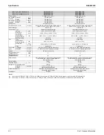
1.2 Indoor
Unit
1. R1T is for remote controller thermistor or optional remote sensor.
No. in
piping
diagram
Name
Symbol
Function
Except
FXMQ-PB
FXTQ-TA
CXTQ-TA
FXMQ-PB
FXTQ-TA
CXTQ-TA
(1)
Electronic expansion valve
Y1E
Y1E
Y1E
Used for gas superheating degree control while in
cooling or subcooling degree control while in
heating.
(2)
Suction air thermistor
R1T
R1T
R1T (
1)
Used for thermostat control.
(3)
Liquid pipe thermistor
R2T
R2T
R2T
Used for gas superheating degree control while in
cooling or subcooling degree control while in
heating.
(4)
Gas pipe thermistor
R3T
R3T
R3T
Used for gas superheating degree control while in
cooling.
(5)
Discharge air thermistor
—
R4T
—
Used for discharge air temperature control.
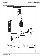
FXFQ-T, FXHQ-M
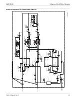
FXZQ-TB
FXUQ-PA
FXEQ-P, FXMQ-M, FXAQ-P, FXLQ-M, FXNQ-M
C: 4D024460P
(4)
(3)
Indoor heat exchanger
Fan
Filter
Filter
(1)
Gas piping
connection port
Liquid piping
connection port
(2)
(4)
(1)
(2)
(3)
C: 4D137354
C: 4D133246
(4)
(2)
(1)
(3)
)LOWHU
+HDWH[FKDQJHU
/LTXLGSLSH
FRQQHFWLRQSRUW
)LOWHU
)DQ
(OHFWURQLF
H[SDQVLRQYDOYH
0
*DVSLSH
FRQQHFWLRQSRUW
Indoor heat exchanger
Fan
Filter
Filter
(4)
(2)
(1)
(3)
Gas piping
connection port
Liquid piping
connection port
C: 4D034245S
Summary of Contents for VRV EMERION RXYQ-AATJA
Page 1: ...Service Manual Heat Pump 60 Hz RXYQ AATJA 208 230 V RXYQ AAYDA 460 V SiUS342303E...
Page 410: ...Wiring Diagrams SiUS342303E 403 Part 7 Appendix FXEQ07 09 12 15 18 24PVJU 3D098557A...
Page 411: ...SiUS342303E Wiring Diagrams Part 7 Appendix 404 FXDQ07 09 12 18 24MVJU C 3D050501C...
Page 416: ...Wiring Diagrams SiUS342303E 409 Part 7 Appendix FXHQ12 24 36MVJU 3D048116C...
Page 417: ...SiUS342303E Wiring Diagrams Part 7 Appendix 410 FXAQ07 09 12 18 24PVJU 3D075354F...
Page 424: ...Wiring Diagrams SiUS342303E 417 Part 7 Appendix VAM1200GVJU 3D073270D...