Installer reference guide
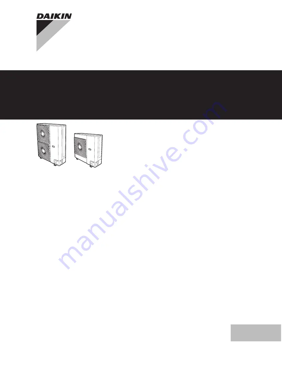
Split system air conditioners
English
RZAG71L7V1B RZAG100L7V1B RZAG125L7V1B RZAG140L7V1B
Page 1: ...Installer reference guide Split system air conditioners English Installer reference guide Split system air conditioners RZAG71L7V1B RZAG100L7V1B RZAG125L7V1B RZAG140L7V1B ...
Page 2: ...iping to the outdoor unit 14 6 4 9 To determine if oil traps are required 15 6 5 Checking the refrigerant piping 16 6 5 1 About checking the refrigerant piping 16 6 5 2 Precautions when checking the refrigerant piping 16 6 5 3 Checking refrigerant piping Setup 16 6 5 4 To check for leaks 16 6 5 5 To perform vacuum drying 16 6 6 Charging refrigerant 17 6 6 1 About charging refrigerant 17 6 6 2 Abou...
Page 3: ...ime to return to normal temperature If you must touch it wear protective gloves Do NOT touch any accidental leaking refrigerant WARNING Provide adequate measures to prevent that the unit can be used as a shelter by small animals Small animals that make contact with electrical parts can cause malfunctions smoke or fire CAUTION Do NOT touch the air inlet or aluminum fins of the unit NOTICE Do NOT pl...
Page 4: ...on pipe sizes and pipe lengths some systems require additional charging of refrigerant Only use tools exclusively for the refrigerant type used in the system this to ensure pressure resistance and prevent foreign materials from entering into the system Charge the liquid refrigerant as follows If Then A siphon tube is present i e the cylinder is marked with Liquid filling siphon attached Charge wit...
Page 5: ...o high frequency electric noise to avoid unnecessary opening of the earth leakage protector NOTICE Precautions when laying power wiring Do not connect wiring of different thicknesses to the power terminal block slack in the power wiring may cause abnormal heat When connecting wiring which is the same thickness do as shown in the figure below For wiring use the designated power wire and connect fir...
Page 6: ...fter it is installed Hand over to the user What to give and explain to the user Maintenance and service How to maintain and service the units Troubleshooting What to do in case of problems Disposal How to dispose of the system Technical data Specifications of the system Glossary Definition of terms 3 About the box 3 1 Overview About the box This chapter describes what you have to do after the box ...
Page 7: ...he demand adaptor kit For installation instructions see the installation manual of the bottom plate heater Demand adaptor kit SB KRP58M51 Can be used for the following Low noise To lower the operation sound of the outdoor unit I demand function To limit the power consumption from the system example budget control limit power consumption during peak moments In combination with a bottom plate heater...
Page 8: ...ons the measured value might be higher than the sound pressure level mentioned in Sound spectrum in the data book due to environmental noise and sound reflections INFORMATION The sound pressure level is less than 70 dBA In places where a mineral oil mist spray or vapour may be present in the atmosphere Plastic parts may deteriorate and fall off or cause water leakage It is NOT recommended to insta...
Page 9: ...table for 1 8 m Floor standing units 1 8 m Wall mounted units 3 Use the graph or table to determine the minimum floor area m kg 0 10 20 30 40 50 60 70 80 90 100 110 120 130 140 150 160 170 180 190 200 210 220 230 240 250 260 270 280 290 300 310 320 330 340 350 360 370 380 390 400 410 420 430 440 450 460 470 480 490 500 510 520 530 540 550 1 1 2 1 4 1 6 1 8 2 2 2 2 4 2 6 2 8 3 3 2 3 4 3 6 3 8 4 4 2...
Page 10: ...ient temperature Humidity Minimum thickness 30 C 75 to 80 RH 15 mm 30 C 80 RH 20 mm 5 4 Preparing electrical wiring 5 4 1 About preparing electrical wiring INFORMATION Also read the precautions and requirements in the General safety precautions chapter INFORMATION Also read 6 7 5 Specifications of standard wiring components on page 19 WARNING If the power supply has a missing or wrong N phase equi...
Page 11: ...roviding drainage 4 Preventing the outdoor unit from falling over 5 Protecting the unit against snow and wind by installing a snow cover and baffle plates See Preparing installation site in 5 Preparation on page 7 6 3 2 Precautions when mounting the outdoor unit INFORMATION Also read the precautions and requirements in the following chapters General safety precautions Preparation 6 3 3 To provide ...
Page 12: ...ating efficiency To prevent this 1 Drill a 4 and remove the knockout hole b b a b 4 Ø6 mm 2 Remove the burrs and paint the edges and areas around the edges using repair paint to prevent rusting 6 3 6 To prevent the outdoor unit from falling over In case the unit is installed in places where strong wind can tilt the unit take following measure 1 Prepare 2 cables as indicated in the following illust...
Page 13: ...Piping size mm Tightening torque N m Flare dimensions A mm Flare shape mm Ø9 5 33 39 12 8 13 2 R 0 4 0 8 45 2 90 2 A Ø15 9 63 75 19 3 19 7 6 4 4 Pipe bending guidelines Use a pipe bender for bending All pipe bends should be as gentle as possible bending radius should be 30 40 mm or larger 6 4 5 To flare the pipe end CAUTION Incomplete flaring may cause refrigerant gas leakage Do NOT re use flares ...
Page 14: ...ssure will be low e g when cooling will be performed while the outside air temperature is low sufficiently seal the flare nut in the stop valve on the gas line with silicon sealant to prevent freezing Silicon sealant make sure there is no gap To open close the stop valve 1 Remove the valve cover 2 Insert a hexagon wrench liquid side 4 mm gas side 6 mm into the valve stem and turn the valve stem Co...
Page 15: ... WARNING Provide adequate measures to prevent that the unit can be used as a shelter by small animals Small animals that make contact with electrical parts can cause malfunctions smoke or fire NOTICE Precautions when making knockout holes Avoid damaging the casing After making the knockout holes we recommend you remove the burrs and paint the edges and areas around the edges using repair paint to ...
Page 16: ...ant R32 tank siphon system e Vacuum pump f Liquid line stop valve g Gas line stop valve A Valve A B Valve B C Valve C Valve State of valve Valve A Open Valve B Open Valve C Open Liquid line stop valve Close Gas line stop valve Close NOTICE Indoor units should also be leak and vacuum tested Keep any possible field supplied field piping valves open as well 6 5 4 To check for leaks NOTICE Do NOT exce...
Page 17: ...igerant piping is performed NOTICE Before completely recharging perform vacuum drying on the outdoor unit s internal refrigerant piping as well To do so use the internal service port of the outdoor unit between the heat exchanger and the 4 way valve Do NOT use the service ports of the stop valves because vacuum drying cannot be performed properly from these ports WARNING Some sections of the refri...
Page 18: ...refrigerant Setup See 6 5 3 Checking refrigerant piping Setup on page 16 6 6 7 To charge refrigerant WARNING Only use R32 as refrigerant Other substances may cause explosions and accidents R32 contains fluorinated greenhouse gases Its global warming potential GWP value is 675 Do NOT vent these gases into the atmosphere When charging refrigerant always use protective gloves and safety glasses CAUTI...
Page 19: ... unit or when in thermostat stop operation 6 7 4 Guidelines when connecting the electrical wiring Keep the following in mind If stranded conductor wires are being used install a round crimp style terminal on the tip Place the round crimp style terminal on the wire up to the covered part and fasten the terminal with the appropriate tool b a a Stranded conductor wire b Round crimp style terminal Use...
Page 20: ...b Interconnection cable Connecting to the frame When cables are routed from the unit a protection sleeve for the conduits PG insertions can be inserted at the knockout hole When you do not use a wire conduit protect the wires with vinyl tubes to prevent the edge of the knockout hole from cutting the wires a b c d e A B A Inside of the outdoor unit B Outside of the outdoor unit a Wire b Bush c Nut ...
Page 21: ...CE Cooling operation mode Perform the test run in cooling operation mode so that stop valves failing to open can be detected Even if the user interface was set to heating operation mode the unit will run in cooling operation mode during 2 3 minutes although the user interface will display the heating icon and then automatically switch to heating operation mode NOTICE If you cannot operate the unit...
Page 22: ...Check operation for 3 minutes 4 Check operation of the airflow direction Action Result 1 Press Return Setting Return Setting Air Volume direction Air Volume Direction Position 0 Low 2 Select Position 0 Return Setting Return Setting Air Volume direction Air Volume Direction Low Position 0 3 Change the position If the airflow flap of the indoor unit moves operation is OK If not operation is not OK 4...
Page 23: ...Before performing any maintenance or service work touch a metal part of the unit in order to eliminate static electricity and to protect the PCB 9 3 Checklist for yearly maintenance of the outdoor unit Check the following at least once a year Outdoor unit heat exchanger The heat exchanger of the outdoor unit can get blocked up due to dust dirt leaves etc It is recommended to clean the heat exchang...
Page 24: ... are open 3 Press the pump down button BS4 for at least 8 seconds BS4 is located on the PCB in the outdoor unit see wiring diagram Result The compressor and outdoor unit fan start automatically and the indoor unit fan might start automatically 4 2 minutes after the compressor started close the liquid stop valve If it is not closed properly during compressor operation the system cannot be pumped do...
Page 25: ... Outdoor unit RZAG71 dimensions in mm h e e f g e f g a b d c 3D103893 i 52 13 67 53 223 95 55 84 55 19 80 145 53 95 19 89 142 53 95 88 60 28 990 940 32 345 340 350 160 620 160 37 91 30 320 30 37 52 40 32 191 154 179 36 6 19 99 16 16 331 337 71 58 a Gas pipe connection Ø15 9 flare connection b Liquid pipe connection Ø9 5 flare connection c Internal service port in the unit d Earthing terminal M5 i...
Page 26: ...13 53 223 95 55 345 340 350 160 620 160 37 52 30 320 30 37 91 40 32 191 154 179 36 6 19 99 16 58 16 71 67 3D103894 a Gas pipe connection Ø15 9 flare connection b Liquid pipe connection Ø9 5 flare connection c Internal service port in the unit d Earthing terminal M5 in the switch box e Refrigerant piping intake f Power supply wiring intake knockout hole Ø34 g Control wiring intake knockout hole Ø27...
Page 27: ... B D 100 100 B D E HB HD HB HD HB HU 250 750 1000 500 HU HB HU 250 1000 1000 500 HB HU HD HU HD HU HB HD HB HD HB HD HB HD HD HU 100 1000 1000 500 HU HD HU 200 1000 1000 500 HD HU HU a b 100 100 c d e eB eD A B C D E HB HD A B C 200 300 1000 A B C E 200 300 1000 1000 500 D 1000 D E 1000 1000 500 B D HD HU 300 1000 HD HU 250 1500 HU HD HU 300 1500 B D E HB HD HB HU 300 1000 1000 500 HU HB HU 300 12...
Page 28: ... If there is danger of drainage dripping and freezing between the upper and lower units A2 Then install a roof between the upper and lower units Install the upper unit high enough above the lower unit to prevent ice buildup at the upper unit s bottom plate B1 B2 B1 If there is no danger of drainage dripping and freezing between the upper and lower units B2 Then it is not required to install a roof...
Page 29: ...iver f Stop valve with service port liquid g Stop valve with service port gas h Cable tie mountings to fix the field wiring with cable ties to ensure stress relief i Compressor accumulator A1P Printed circuit board main M1C Motor compressor M1F Motor fan S1PH A Automatic high pressure switch S1PH M Manual high pressure switch S1PL Low pressure switch X1M Terminal communication and power supply Y1E...
Page 30: ...service port liquid g Stop valve with service port gas h Cable tie mountings to fix the field wiring with cable ties to ensure stress relief i Compressor accumulator A1P Printed circuit board main M1C Motor compressor M1F Motor upper fan M2F Motor lower fan S1PH A Automatic high pressure switch S1PH M Manual high pressure switch S1PL Low pressure switch X1M Terminal communication and power supply ...
Page 31: ... Switch box cooling f Pressure regulating valve g Heat exchanger h Internal service port 5 16 i Check valve j Compressor accumulator k Liquid receiver l Capillary tube M1C Motor compressor R1T Thermistor air R2T Thermistor discharge R3T Thermistor suction R4T Thermistor heat exchanger inlet R5T Thermistor heat exchanger middle R6T Thermistor liquid S1PH A Automatic high pressure switch S1PH M Manu...
Page 32: ...H A P P P L1R A1P X1M HAP A2P F8U F7U E1H HAP L1R K10R K11M V2R R7T F6U K13R R4 V1D R5 X106A V1R 2 1 6 8 6 Q1DI DS1 X1M t 3 MS W V U Electronic component assembly Position of elements Rear view Front view See note 7 Position of compressor terminal Notes 1 Symbols see below 2 Colours see below 3 This wiring diagram applies only to the outdoor unit 4 Refer to the wiring diagram sticker on the back o...
Page 33: ... Reactor M1C Motor compressor M1F Motor fan PS Switching power supply Q1DI Earth leakage circuit breaker 30 mA R2 R5 R6 Resistor R1T Thermistor air R2T Thermistor discharge R3T Thermistor suction R4T Thermistor heat exchanger inlet R5T Thermistor heat exchanger middle R6T Thermistor liquid R7T R8T Thermistor Positive Temperature Coefficient RC Signal receiver circuit S1PH A Automatic high pressure...
Page 34: ... 2 3 1 Electronic component assembly Position of elements Rear view Front view See note 7 See note 7 Position of compressor terminal Notes 1 Symbols see below 2 Colours see below 3 This wiring diagram applies only to the outdoor unit 4 Refer to the wiring diagram sticker on the back of the service cover for how to use the BS1 BS4 and DS1 switches 5 When operating do not short circuit protective de...
Page 35: ...PS Switching power supply Q1DI Earth leakage circuit breaker 30 mA R1 R5 Resistor R1T Thermistor air R2T Thermistor discharge R3T Thermistor suction R4T Thermistor heat exchanger inlet R5T Thermistor heat exchanger middle R6T Thermistor liquid R7T Thermistor fin RC Signal receiver circuit S1PH A Automatic high pressure switch S1PH M Manual high pressure switch S1PL Low pressure switch TC Signal tr...
Page 36: ...direction Horizontal Motor Quantity 1 2 Model Brushless DC motor Output 94 W Drive Direct drive Compressor Quantity 1 Motor Type Hermetically sealed swing compressor Starting method Inverter driven Operation range Cooling Minimum See operation range drawing Maximum Heating Minimum Maximum Sound level Nominal Cooling Sound power 64 dBA 66 dBA 67 dBA 69 dBA Sound pressure 48 dBA 50 dBA 51 dBA 52 dBA...
Page 37: ...apacity control method Inverter controlled Safety devices Manual high pressure switch Automatic high pressure switch low pressure switch fan driver overload protector fuse Electrical specifications RZAG71 RZAG100 RZAG125 RZAG140 Power supply Name V1 Phase 1 Frequency 50 Hz Voltage 220 240 V Voltage range Minimum 198 V Maximum 264 V Current Minimum Ssc value Equipment complying with EN 61000 3 12 a...
Page 38: ...d service to the product Installation manual Instruction manual specified for a certain product or application explaining how to install configure and maintain it Operation manual Instruction manual specified for a certain product or application explaining how to operate it Accessories Labels manuals information sheets and equipment that are delivered with the product and that need to be installed...
Page 39: ......
Page 40: ...4P418663 1 2016 02 Copyright 2016 Daikin ...