Installation and Maintenance Manual IM 1267-7
Group:
Applied Terminal Systems
Part Number:
IM1267-7
Date:
February 2023
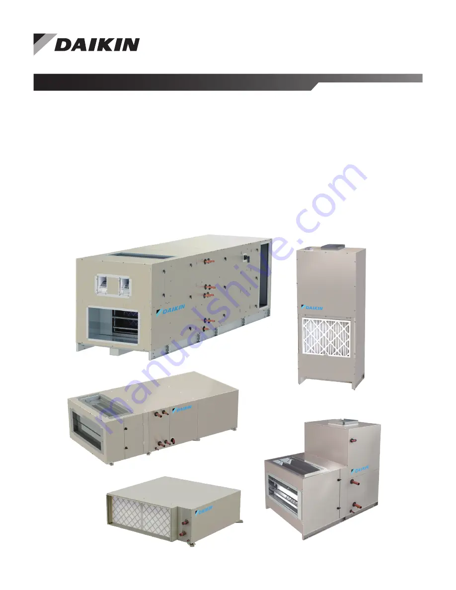
PreciseLine® Air Handler
Sizes 006 through 100
Page 1: ...Installation and Maintenance Manual IM 1267 7 Group Applied Terminal Systems Part Number IM1267 7 Date February 2023 PreciseLine Air Handler Sizes 006 through 100...
Page 2: ...Vertical Filter Data 67 Thermal Expansion Valve Kits 70 Mixing Box Optional 74 Dimensional Data 75 Size 006 050 Horizontal Unit Dimensions 75 Size 006 050 Vertical Unit Dimensions 84 Size 060 100 Uni...
Page 3: ...s Size 030 and larger Smoke Control and Management Systems WARNING Improper smoke or fume air handling can result in severe personal injury or death A registered professional engineer must design and...
Page 4: ...3 L 230 60 3 T 460 60 3 W 575 60 3 Primary Coil Connection Location L Left Hand Air back of the head R Right Hand Air back of the head C Center Category Code Description Primary Coil Type W Water Glyc...
Page 5: ...nit must be turned over or tilted up to access the bottom screws care must be used to avoid damage CAUTION Sharp edges can cause personal injury Avoid contact with them Use care and wear protective cl...
Page 6: ...spection cleaning Provide sufficient space on the controls access side of the unit for filter replacement drain pan cleaning and coil removal if necessary For routine maintenance remove service panels...
Page 7: ...Sizes 030 040 and 050 Width of Coil Section Depth of Unit Filter Length Filter Depth Table 1 Bottom Filter Access Clearance 006 008 010 012 016 018 020 030 040 050 Cabinet 30L 15W 18H 30L 20W 18H 30L...
Page 8: ...Clearance and Access Requirements for Vertical Units NOTE AVD units require field cut holes on the sides or back depending on piping orientation These holes should either be drilled prior to unit ins...
Page 9: ...Installation www DaikinApplied com 9 IM 1267 7 PRECISELINE AIR HANDLER Figure 7 Clearance for Filter Access from Top Unit Size 030 050 Figure 8 Clearance and Access Requirements for Unit Sizes 060 100...
Page 10: ...ger is responsible for developing a safe lift plan to meet local national international codes WARNING Use all lifting points Improper lifting can cause severe personal injury death or property damage...
Page 11: ...rigged and completely assembled The PreciseLine air handler main section should be positioned on the pallet to permit access to mounting holes in the structural cross bracing under the unit The entire...
Page 12: ...let and secured with minimum 1 2 threaded rod washers and lock nuts through all support bracing If the pallet is not available the fully assembled unit may be supported by the main section while lifti...
Page 13: ...have any internal vibration isolation Unit Sizes 030 040 050 Mounting the Unit on the Floor Vertical units are all floor mounted and horizontal units may be floor mounted as well Spring Mount Sizes 0...
Page 14: ...an cause misfit between sections cabinet leaks binding of the doors and access panels and prevent proper draining of drain pans Vertical Units Size 006 020 and Horizontal Units 060 100 come with level...
Page 15: ...16 18 20 36 38 Figure 21 Baserail Hole Length Panels and Doors PreciseLine air handlers have hinged access doors or screw on panels that can be easily removed and handled To gain access through a side...
Page 16: ...n Figure 24 Door Access Types Sizes 060 100 Figure 25 Side Filter Access Sizes 030 050 Horizontal Figure 26 Top Filter Access Sizes 030 050 Horizontal Figure 27 Bottom Filter Access Sizes 030 050 Hori...
Page 17: ...267 7 PRECISELINE AIR HANDLER Figure 29 Accessing Internal Filter Sizes 006 020 Vertical Figure 30 Filter Side Access Sizes 030 050 Vertical Figure 31 2 Fan Fillter Top Removal Sizes 006 020 Vertical...
Page 18: ...air below 40 F is not recommended Extended periods of temperatures below freezing can cause some components to function improperly 5 If fresh air and return air are to be heated by a hot water coil t...
Page 19: ...ing penetration holes must be field drilled in the location of the pilot holes The diameter of the hole should be no more than 1 2 larger than the pipe and the gap around the pipe should be sealed aft...
Page 20: ...and must be completely within the drill area on the factory designated panel The diameter of the hole should be no more than 1 2 larger than the pipe and gap around the pipe should be sealed after ins...
Page 21: ...Size 006 008 010 012 016 018 020 A 7 13 7 80 7 62 7 53 Figure 41 Horizontal Units Sizes 006 020 DX Coil with Reheat or Preheat Drill Area Table 7 Horizontal Units Sizes 006 020 DX Coil with Reheat or...
Page 22: ...Size X M 30 27 13 6 61 40 30 14 7 65 50 30 14 6 62 Interlaced DX Primary with 1 Row Hydronic Reheat 30 27 13 7 35 40 30 14 7 62 50 30 14 7 35 Single Circuit DX Primary with 2 Row Hydronic Reheat 30 27...
Page 23: ...y The valve flow coefficient and connection ports are appropriately sized for the selected flow rate The control actuator can be configured for spring return on off normally closed to the coil spring...
Page 24: ...s water flow away from coil in response to 24V or line voltage signal Includes fixed orifice for balancing PT Port For connecting a pressure or temperature gauge Y Strainer Removable screen filters ou...
Page 25: ...2 Way 0 5 FPT 16 On Off 24V Yes Normally open B216B TFRB24 DKN 263940314 2 Way 0 75 FPT 24 On Off 24V Yes Normally Closed B221B LF24 DKN 263940306 2 Way 0 75 FPT 24 On Off 24V Yes Normally open B221B...
Page 26: ...No N A B222 LRB24 SR DKN 263941202 2 Way 1 00 FPT 10 Modulating 0 10VDC No N A B223 LRB24 SR DKN 263941203 2 Way 1 00 FPT 30 Modulating 0 10VDC No N A B225 LRB24 SR DKN 263940501 3 Way 0 50 FPT 0 3 Mo...
Page 27: ...GPM 0 5 0 75 1 0 8 00 263578315 263578415 263578502 9 00 263578316 263578416 263578503 10 00 263578504 10 50 263578317 263578417 11 00 263578318 263578418 12 00 263578319 263578419 15 00 263578505 18...
Page 28: ...IM 1267 7 PRECISELINE AIR HANDLER 28 www DaikinApplied com Installation Manual Circuit Setter Flow Charts Figure 55 Manual Circuit Setter Flow Chart 1 2 Valves...
Page 29: ...Installation www DaikinApplied com 29 IM 1267 7 PRECISELINE AIR HANDLER Figure 56 Manual Circuit Setter Flow Chart 3 4 and 1 Valves...
Page 30: ...ous combinations of EAT and kW are provided beginning on Table 17 on page 31 or may be calculated using the equation below LAT kW 3145 622 CFM EAT Electric Heat Safety Overcurrent Protection Optional...
Page 31: ...00 600 600 800 1000 1000 2 300 400 600 600 800 1000 1000 2 45 300 400 600 600 800 1000 1000 3 300 400 600 600 800 1000 1000 3 27 300 400 600 600 800 1000 1000 4 300 400 600 600 800 1000 1000 4 09 300...
Page 32: ...400 3000 17 3600 18 1500 2000 2500 1800 2400 3000 19 3600 20 3600 21 1500 2000 2500 1800 2400 3000 24 1500 2000 2500 1800 2400 3000 25 4800 28 9 4800 6000 30 2000 2500 2400 3000 32 4800 6000 34 4 3600...
Page 33: ...0 1000 10 575 600 800 1000 12 800 1000 19 2 1100 kW Forward Curved Fan Units Plenum Fan Units 030 040 050 030 040 050 Air Volume CFM Air Volume CFM 6 8 1500 2000 2500 1800 2400 3000 9 1500 2000 2500 1...
Page 34: ...8 1 6 3 3 4 9 6 5 8 2 230 60 1 1 0 2 0 4 0 6 0 8 0 10 0 277 60 1 1 0 2 0 4 0 6 0 8 0 10 0 12 0 13 0 460 60 1 4 0 8 0 10 0 12 0 16 0 20 0 018 120 60 1 1 0 2 0 4 0 5 0 208 60 1 0 8 1 6 3 3 4 9 6 5 8 2...
Page 35: ...1 2 0 4 0 8 0 10 0 277 60 1 2 0 4 0 8 0 10 0 460 60 1 2 0 4 0 5 0 8 0 10 0 016 120 60 1 2 0 4 0 208 60 1 3 3 6 5 8 2 230 60 1 4 0 8 0 10 0 277 60 1 4 0 8 0 10 0 12 0 460 60 1 4 0 8 0 10 0 12 0 020 120...
Page 36: ...05 9 81 47 16 18 39 13 13 31 27 16 32 13 05 10 63 51 11 21 45 65 15 36 08 18 83 15 06 11 30 54 33 18 43 30 22 59 18 07 13 50 64 90 19 45 70 17 2 47 70 20 24 10 19 20 28 9 80 30 21 26 36 21 09 34 4 95...
Page 37: ...nameplate and be in conformance with the National Electric Code and local restrictions 2 The unit metal frame must be connected to the building electrical ground and all wiring must be in conformance...
Page 38: ...op View Return AA BB Access Discharge Field cut up to 1 diameter electrical service Note Left hand unit shown right hand unit values same as left but opposite Figure 59 Figure 58 Letter Dimensions Uni...
Page 39: ...signal applied to terminal VLV1 24 or VLV2 24 to control the valve 3 Analog control requires a 0 10VDC signal applied to terminal VLV1 0 10V or VLV2 0 10V to modulate the valve Motor Controls 1 Unit s...
Page 40: ...ion is complete PreciseLine units are available with several control schemes which may require low voltage field wiring Use the Unit Specific Electrical Schematics to determine which control connectio...
Page 41: ...Signal 0 10VDC Output 277 Outdoor Air Damper 0 10VDC Output 281 Discharge Air Temp Thermistor Input 282 Return Air Temp Thermistor Input 297 Outdoor Air Temp Thermistor Input 299 Emergency Stop Discre...
Page 42: ...ot be mounted in recesses shelving behind curtains or doors or above or near direct heat sources Avoid direct sun and draught The conduit must be sealed on the device side as currents of air in the co...
Page 43: ...Connect the wires to the sensor as follows H23V 24VDC Supply HCOM Sensor Common Ground HSIG Space Humidty Sensor Duct Static Pressure Sensor Additional Required Parts 4 10 x self tapping sheet metal...
Page 44: ...ssure See Figure 71 Figure 72 Secure Sensor with Provided Screws Blue Green White Connect the wires to the sensor as follows See Figure 73 White to Vout DSP Input Green to GND Sensor Common Ground Blu...
Page 45: ...ions and a separate twisted pair for the power wire connections The shield should be earth grounded only at the power source Larger gauge wire may be required for runs greater than 250 CAUTION The AC...
Page 46: ...witch Installation Two field provided duct pressure taps will be required to install this sensor Locate one tap in the ductwork upstream of the fan and the second downstream of the fan Mount sensor on...
Page 47: ...ired 2 Differentiate between the duct pressure HI and reference pressure LO taps by using different color tubing or by tagging the tubes Daikin Applied recommends 3 16 I D plastic tubing 3 Locate the...
Page 48: ...mperature Sensor Mounting Measurements MicroTech 4 Lite Portable Interface WARNING Electric shock hazard Can cause death personal injury or equipment damage This equipment must be properly grounded Co...
Page 49: ...ing the text is white with a black box around it When the line contains a changeable value and the cursor is at that line the entire line is highlighted Each line on a page may also be defined as a ju...
Page 50: ...password until either the password timer expires or a different password is entered The default value for this password timer is 10 minutes It is changeable from 3 to 30 minutes via the Timer Settings...
Page 51: ...etpoint by more than half the occupied cooling deadband The economizer operation is not disabled Compressor Operation Single Compressor In this configuration a single output is used for compressor con...
Page 52: ...fication is only available when the unit is in the cooling state When dehumidification is enabled operation is initiated when Humidity Control is set to either Relative Humidity or Dew Point and that...
Page 53: ...s of operation and the wiring diagrams to become familiar with the functions and purposes of the controls and devices 13 Determine which optional controls are included with the unit Initial Manual Mod...
Page 54: ...trol Manual Ctrl Type Heating a The fan will activate b If present the hot water valves will open c If present electric heat outputs will stage on Alternativly individual outputs can be commanded on u...
Page 55: ...Date b Set the operating schedule as required using keypad menus Main Menu ViewStatus Date Time and Date Time Schedules NOTE When used with a Building Automation System these settings may need to be k...
Page 56: ...Intermediate Electric Heat Terminal Block EWT Entering Water Temperature TB6 No Controls Terminal Block FM1 2 Fan Motor RAT Return Air Temperature Sensor FRZ Freeze Alarm Switch R1 2 Electric Heater...
Page 57: ...Elements LVB Low Voltage Control Board MIII MicroTech III Control Board NCB Network Communication Board OAT Outside Air Temperature Sensor OHA Automatic High Temp Cutout Switch OHM Manual High Temp Cu...
Page 58: ...minal Block EB MicroTech III I O Expansion Board TB5 Intermediate Electric Heat Terminal Block EWT Entering Water Temperature TB6 No Controls Terminal Block FM1 2 Fan Motor RAT Return Air Temperature...
Page 59: ...inApplied com 59 IM 1267 7 PRECISELINE AIR HANDLER NOTE Wiring diagrams are typical always defer to the wiring diagram provided with the unit 3 Phase Power Welded Aluminum Airfoil Plenum Fan On Off El...
Page 60: ...PRECISELINE AIR HANDLER 60 www DaikinApplied com Example Wiring Diagrams NOTE Wiring diagrams are typical always defer to the wiring diagram provided with the unit MicroTech 4 Lite Controller for Size...
Page 61: ...ring Diagrams www DaikinApplied com 61 IM 1267 7 PRECISELINE AIR HANDLER NOTE Wiring diagrams are typical always defer to the wiring diagram provided with the unit MicroTech 4 Lite Controller for Size...
Page 62: ...PRECISELINE AIR HANDLER 62 www DaikinApplied com Example Wiring Diagrams NOTE Wiring diagrams are typical always defer to the wiring diagram provided with the unit MicroTech 4 Lite Controller for Size...
Page 63: ...Coil Dry 2 12 7 4 8 4 10 5 10 5 12 6 14 7 14 7 24 11 32 15 39 18 Coil Dry 2 16 7 4 8 4 11 5 11 5 14 7 16 8 16 8 27 13 35 16 43 20 Coil Dry 4 12 10 5 12 6 16 8 16 8 20 10 25 12 25 12 41 19 55 25 65 30...
Page 64: ...39 352 160 378 171 Fan Section 422 191 415 188 457 207 Single Supply Fan Weight 110 50 110 50 110 50 Dual Supply Fan Weight 220 100 220 100 220 100 Coil Section 130 59 140 64 166 75 Prefilter 234 106...
Page 65: ...3 16 40 19 52 24 66 30 DX Normal 6 12 14 7 19 9 26 12 35 16 42 20 67 31 85 39 107 49 DX Interlaced 6 12 64 30 84 39 107 49 DX Normal 6 14 15 7 20 10 27 13 37 17 44 20 71 33 90 41 113 52 DX Interlaced...
Page 66: ...Fan and Motor Data Plenum Supply Fans Plenum Fan Data Unit Size 060 080 100 Fan Quantity 1 or 2 1 or 2 1 or 2 Fan Type Plenum Fan Plenum Fan Plenum Fan Fan Size 450 mm 450 mm 450 mm Maximum RPM 2600...
Page 67: ...050 060 080 100 Connection Type FPT Nominal F SWT OD 2 Row Cooling 0 500 0 500 0 500 0 500 0 750 0 750 0 750 1 125 1 125 1 375 1 125 1 125 1 375 4 Row Cooling 0 500 0 500 0 750 0 750 0 750 1 000 1 00...
Page 68: ...500 0 500 0 500 0 500 0 500 0 500 1 125 1 125 1 375 1 125 1 125 1 375 NOTE Number of connections in unit sizes 060 100 are doubled stacked Table 43 Horizontal Steam Coil Size and Type with No Piping...
Page 69: ...ormal 0 875 1 375 020 6 1 Normal 0 875 1 375 030 3 1 Normal 0 875 1 625 030 3 2 Interlaced 0 625 0 875 030 6 1 Normal 030 6 2 Interlaced 0 875 0 875 040 3 1 Normal 0 875 1 625 040 3 2 Interlaced 0 875...
Page 70: ...0 BBIZE 4 263922466 BBIZE 5 263922467 16 0 500 0 500 BBIZE 4 263922466 BBIZE 5 263922467 18 12 0 625 0 500 BBIZE 5 263922466 BBIZE 6 263922467 16 0 625 0 500 BBIZE 5 263922466 BBIZE 6 263922467 20 12...
Page 71: ...16 B 0 625 0 625 BBIZE 6 263922471 BBIZE 8 263922485 60 12 A C 0 500 0 500 BBIZE 3 263922465 BBIZE 4 263922466 12 B D 0 500 0 500 BBIZE 3 263922465 BBIZE 4 263922466 16 A C 0 500 0 500 BBIZE 4 2639224...
Page 72: ...BBIZE 3 263922465 16 0 500 0 500 BBIZE 3 263922465 012 6 12 0 625 0 625 BBIZE 4 910279782 14 0 625 0 625 BBIZE 4 910279782 16 0 625 0 625 BBIZE 4 910279782 016 3 12 0 625 0 625 BBIZE 4 910279782 14 0...
Page 73: ...82 14 B 0 625 0 875 BBIZE 5 910279777 16 A 0 625 0 875 BBIZE 6 263922482 16 B 0 625 0 875 BBIZE 5 910279777 040 6 12 A 0 875 0 875 BBIZE 8 910279795 12 B 0 875 0 875 BBIZE 8 910279795 14 A 0 875 0 875...
Page 74: ...For the mixing box ordered without the factory mounted damper actuator one must be provided in the field that meets the following criteria Maximum range of rotation 95 Maximum torque 62 in lbs On off...
Page 75: ...AIR FLOW Note Left hand unit shown right hand unit same as left but opposite Cabinet Sizes 006 008 010 012 Top View Cabinet Length Cabinet Length Cabinet Height Cabinet Width Cabinet Width V T L Q Q R...
Page 76: ...1 83 1 83 1 83 1 83 L 1 70 1 38 2 42 2 42 1 79 1 18 1 18 M 11 61 16 61 26 87 26 87 35 27 43 87 43 87 N 0 67 0 59 0 60 0 60 0 60 0 60 0 60 P 16 97 16 97 16 97 16 97 16 97 16 97 16 97 Q 9 56 9 53 9 53...
Page 77: ...ight Z 1 00 Base 563 Mntg Holes 4 X T V AA Cabinet Length Cabinet Width Q 5 0 R 75 Drain Primary Supply Secondary Return Optional Primary Return Secondary Supply Optional Front View Left Side View Top...
Page 78: ...8 5 28 5 28 5 28 5 28 5 30 43 30 5 30 5 28 5 28 5 30 43 30 5 30 5 28 25 28 25 32 16 E 34 5 34 5 32 67 34 5 34 5 34 5 34 62 32 62 34 5 34 5 34 62 34 62 G 4 62 4 62 4 62 4 62 4 62 4 62 4 62 4 62 4 62 4...
Page 79: ...7 34 48 34 7 32 85 32 85 F 4 35 4 35 4 35 5 65 4 62 5 35 5 35 5 35 5 62 4 62 G 5 62 4 62 4 39 4 35 9 35 5 62 4 62 5 35 5 35 H 25 38 26 87 9 35 9 35 25 37 26 87 J 25 37 26 87 25 37 26 87 9 35 9 35 050...
Page 80: ...e Cabinet 006 008 010 012 016 018 020 030 040 050 B 6 64 6 64 6 64 6 64 6 64 6 64 6 64 5 54 5 54 5 54 C 13 47 13 47 13 47 13 47 13 47 13 47 13 47 18 39 18 39 18 39 D 2 11 2 11 2 11 2 11 2 11 2 11 2 11...
Page 81: ...0 030 040 050 A 20 51 20 51 20 51 20 51 20 51 20 51 20 51 27 27 27 27 27 27 B 6 64 6 64 6 64 6 64 6 64 6 64 6 64 5 54 5 54 5 54 C 13 47 13 47 13 47 13 47 13 47 13 47 13 47 18 39 18 39 18 39 D 2 11 2 1...
Page 82: ...64 6 64 6 64 6 64 6 64 6 64 5 54 5 54 5 54 C 13 47 13 47 13 47 13 47 13 47 13 47 13 47 18 39 18 39 18 39 D 2 11 2 11 2 11 2 11 2 11 2 11 2 11 3 80 5 80 6 80 E 13 47 13 47 13 47 13 47 13 47 13 47 13 47...
Page 83: ...0 14 00 16 00 20 00 20 00 24 00 24 00 28 00 NOTE Discharge opening is offered on any one particular side but is shown here on all availabe surfaces for dimensioning purposes only A discharge plenum is...
Page 84: ...N A 8 47 8 06 0 63 11 75 008 18 00 28 00 65 00 2 54 6 65 N A 13 50 19 04 11 50 3 50 10 86 4 76 2 81 2 85 N A 9 97 8 06 0 63 11 75 012 18 00 31 50 67 00 2 54 7 83 N A 13 50 21 75 11 50 3 50 10 86 4 76...
Page 85: ...ea 20 00 Field Access Area J K G R Q P O N Note Right Hand Cabinet Shown Left Hand Similar But Opposite 750 Drain T Dia Optional 2 Disconnect Switch 1 00 HH GG A Max Length Cabinet Length 1 50 1 50 B...
Page 86: ...P Q R S T SIZE 30 5 3 9 22 22 72 7 74 27 59 27 12 24 63 1 125 SIZE 40 5 3 9 22 26 72 5 42 27 59 27 17 24 57 1 375 SIZE 50 5 3 9 22 34 72 5 42 27 59 27 17 24 57 2 125 6 1 Rows Coil RH Re heat K F H G...
Page 87: ...22 72 7 74 27 6 28 09 25 61 23 07 20 47 1 625 1 125 SIZE 40 5 3 9 22 26 72 9 22 26 72 5 42 27 59 28 15 25 55 23 07 20 47 1 625 1 375 SIZE 50 5 3 9 22 34 72 9 22 34 72 5 42 28 15 27 59 25 56 23 07 20...
Page 88: ...9 28 09 25 61 22 64 1 125 SIZE 40 5 3 9 22 26 72 9 84 5 42 27 59 28 15 25 55 22 64 0 875 SIZE 50 5 3 9 22 34 72 9 84 5 42 27 59 27 59 25 56 22 64 1 375 1 DX INTERLACE 3 ROWS COIL RH PRE HEAT K F H G J...
Page 89: ...ng Box Dimension Letter Reference Vertical Mixing Box A B C D I J K L M N O P Q R S T W X SIZE 30 5 5 24 42 5 44 26 31 33 2 87 38 27 3 5 9 82 18 37 31 34 5 36 76 70 12 34 18 37 14 19 SIZE 40 5 5 24 46...
Page 90: ...50 25 00 5 47 20 00 1 75 14 00 6 75 29 00 0 25 18 00 38 00 63 50 33 00 17 50 25 00 2 47 20 00 1 75 14 00 6 00 31 00 0 25 18 00 43 00 64 00 Vertical A B C F G H J L M N Cabinet Length Cabinet Width Ca...
Page 91: ...imensions Figure 99 Coil Section Dimensions Sizes 060 100 Table 65 General Unit Dimensions Sizes 060 100 Length Width Height U V W X Y SIZE 60 28 00 54 00 54 00 4 19 12 39 4 38 62 75 3 50 SIZE 80 28 0...
Page 92: ...25 15 48 16 83 7 61 19 75 6 24 8 83 6 59 22 25 15 48 16 83 7 59 19 75 SIZE 100 5 20 2 03 6 23 8 84 6 11 24 25 15 39 16 84 6 11 24 25 6 23 8 84 6 59 24 25 15 39 16 84 6 59 24 25 4 Row Cold Water 1 Row...
Page 93: ...0 5 20 2 03 7 14 8 59 6 11 24 25 13 49 16 08 6 11 24 25 7 14 8 59 6 59 24 25 13 49 16 08 6 59 24 25 1 Row Hot Water 2 Row Cold Water A B C D E F G H J K L M N P Q R S T SIZE 60 7 34 8 55 6 11 18 39 13...
Page 94: ...5 2 Row Hot Water DX SINGLE A B C D E F G H J K L M N P Q R S T SIZE 60 7 45 9 00 6 11 18 25 13 88 24 63 7 45 9 00 6 59 18 25 13 88 6 33 SIZE 80 7 50 9 04 6 11 22 25 13 92 28 63 7 50 9 04 6 59 22 25 1...
Page 95: ...59 18 25 SIZE 80 7 80 5 49 16 07 13 38 12 61 15 21 6 11 22 25 7 80 5 49 5 50 13 38 12 61 15 21 6 59 22 25 SIZE 100 5 20 2 03 7 80 5 48 17 06 14 65 13 49 16 08 6 11 24 25 7 80 5 48 5 25 14 65 13 49 16...
Page 96: ...nsions Sizes 060 100 Table 69 Mixing Box Dimension Letter Reference Dimension 060 080 100 A 60 00 68 00 72 00 B 54 00 62 00 66 00 C 28 13 28 13 31 63 D 62 75 62 75 69 75 E 54 00 54 00 61 00 F 52 76 52...
Page 97: ...ter Reference Dimension 060 080 100 Dimension 060 080 100 A 30 00 30 00 30 00 K 20 00 24 00 26 00 B 3 00 7 00 2 50 L 3 49 3 49 3 46 C 48 00 48 00 61 00 M 5 50 3 00 3 00 D 18 00 24 00 23 50 N 43 00 48...
Page 98: ...Dimension 060 080 100 Dimension 060 080 100 A 48 00 48 00 48 00 L 3 49 3 49 3 46 B 3 00 7 00 2 50 M 5 50 3 00 3 00 C 48 00 48 00 61 00 N 43 00 48 00 55 00 D 18 00 24 00 23 50 P 62 75 62 75 69 75 E 4...
Page 99: ...on Letter Reference Dimension 060 080 100 1 Fan 2 Fans 2 Fans 3 Fans 2 Fans 3 Fans A 23 20 15 20 15 20 7 20 18 75 10 75 B 7 60 23 60 23 60 39 61 23 50 39 61 C 9 84 9 84 13 84 13 81 15 84 15 81 D 11 26...
Page 100: ...60 100 Table 73 Economizer Section Dimension Letter Reference Dimension 060 080 100 A 7 00 5 00 4 50 B 40 00 44 00 52 00 C 54 00 62 00 66 00 D 23 75 23 75 27 25 E 61 50 69 50 73 50 F 18 00 22 00 23 19...
Page 101: ...LER Figure 105 Return Filter Dimensions Sizes 060 100 Table 74 Return Filter Section Dimension Letter Reference Dimension 060 080 100 A 54 00 62 00 66 00 B 45 36 45 36 52 36 C 28 13 28 13 31 63 D 52 8...
Page 102: ...om Dimensional Data Figure 106 Electric Heat Section Dimensions Sizes 060 100 Table 75 Electric Heat Section Dimension Letter Reference Dimension 060 080 100 A 55 82 55 82 62 82 B 23 75 23 75 27 25 C...
Page 103: ...sion Letter Reference Dimension 060 080 100 A 48 00 48 00 48 00 B 43 65 43 65 43 65 C 36 65 44 64 48 64 D 44 08 52 08 56 07 E 43 65 43 65 43 65 F 29 50 31 00 31 38 G 15 87 14 37 14 57 H 12 25 8 50 8 3...
Page 104: ...IM 1267 7 PRECISELINE AIR HANDLER 104 www DaikinApplied com Dimensional Data Accessory Dimensions Figure 108 Integrated Thermostat Figure 109 Economizer Space Humidity Sensor...
Page 105: ...ing fans lockout and tag out power Before Starting the Unit Make sure that fan electrical power source is disconnected and locked in the OFF position before entering fan section With ductwork connecte...
Page 106: ...nt Removal Hydronic Coil Removal Horizontal Unit Sizes 006 020 1 Remove coil section access panel 2 Drain the coils 3 Disconnect unions on supply and return of heating and cooling coils inside cabinet...
Page 107: ...nside right 3 and inside left 3 holding external filter frame OR 1 Remove screws holding internal filter brackets and bottom panel assembly 2 Remove screws holding upper and lower front panels number...
Page 108: ...ews and Panels 2 Drain coils 3 Disconnect supply and return on heating and cooling coils from field piping 4 Remove any field piping that might be interfere with coil removal 5 Disconnect any damper o...
Page 109: ...cooling coil in the preheat position To separate the electric heat rack from the cooling coil remove the screws on each end of the coil and the connectors Hydronic Coil Removal Vertical Unit Sizes 03...
Page 110: ...using caution to not damage cap tubes 6 Slide out the 2nd position coil Hydronic Coil Removal Sizes 060 100 Primary Coil and Optional Secondary Coil Shown 1 Remove screws securing the access panel to...
Page 111: ...R COIL ASSEMBLY IS HEAVY Failure to use the proper lifting equipment to support the weight of the assembly can cause property damage personal injury or death Supports should be able to lift the weight...
Page 112: ...ottom screws on the upstream side Swing the control box out to make room for the fan housing to slide out 3 Remove the set screw on the fan housing rail and slide out the blower assembly Figure 116 Re...
Page 113: ...bracket and one on the upper back side of the bracket 3 The VFD mounting bracket with the control box wires still attached should be moved out of the way and supported to avoid straining the wires Fi...
Page 114: ...n is straight and centered in the housing 4 Tighten the mounting bolts and shaft set screws 5 Push the sled into the cabinet until it is against the back stop and the fan housing is tight against the...
Page 115: ...bar frame DANGER FAN SLED ASSEMBLY IS HEAVY Failure to use the proper lifting equipment to support the weight of the sled assembly can cause property damage personal injury or death Supports should be...
Page 116: ...Vertical Unit Sizes 006 020 DWDI Forward Curved Fans 1 Remove 2 screws 2 Slide out fan and motor assembly 3 Remove motor mount leg bolts 4 Loosen set screw holding fan to fan shaft 5 Remove motor and...
Page 117: ...orward Curved Fans 1 Remove 4 screws holding VFD controller 2 Remove VFD controller 3 Remove 4 screws along motor sled rails 4 Slide out motor and fan assembly sled 5 Loosen fan wheel set screws 2 on...
Page 118: ...he motor orientation when installing a new fan Matching the motor orientation will ensure wires can reach the connectors of the new motor 4 Secure supports to the metal bar frame DANGER FAN SLED ASSEM...
Page 119: ...e slide out rail DANGER NEVER slide fans out of the cabinet unless the cabinet is securely fastened to a flat surface or to another cabinet section Failure to do so will create tipping hazard which ca...
Page 120: ...nsportation charges must be prepaid The return of the part does not constitute an order for replacement Therefore a purchase order must be entered through the nearest Daikin Applied representative The...
Page 121: ......
Page 122: ...sold pursuant to its standard terms and conditions of sale including Limited Product Warranty Consult your local Daikin Applied representative for warranty details To find your local Daikin Applied r...