background image

17

 | 

Electrical installation

Installer and user reference guide

92

LRYELRNUN5A7Y1

CO₂ Conveni-Pack outdoor unit

4P605460-1 – 2020.08

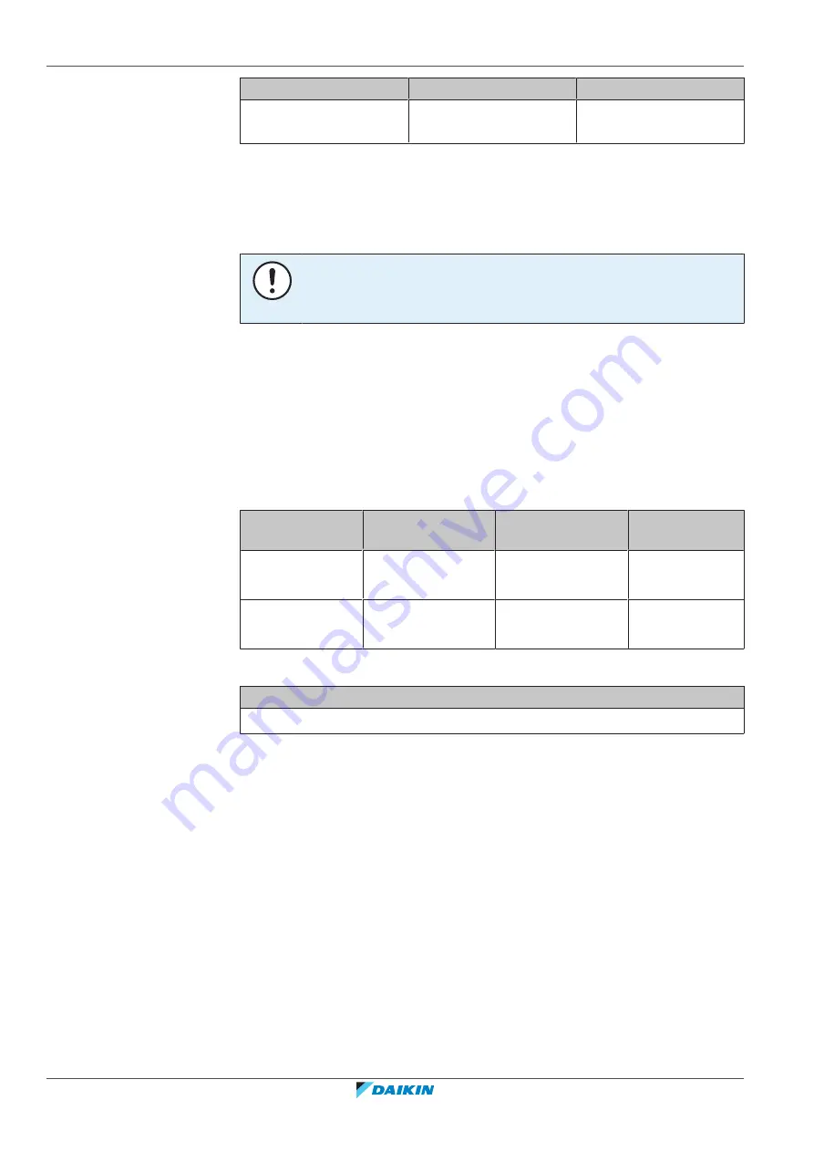
Terminal

Screw size

Tightening torque (N•m)

X1M (A1P): DIII
transmission wiring

M3.5

0.80~0.96

17.5 Specifications of standard wiring components

Power supply

NOTICE

When using residual current operated circuit breakers, be sure to use a high-speed
type 300 mA rated residual operating current.

The power supply must be protected with the required safety devices, i.e. a main
switch,  a  slow  blow  fuse  on  each  phase  and  an  earth  leakage  protector  in
accordance with the applicable legislation.

Selection and sizing of the wiring should be done in accordance with the applicable
legislation based on the information mentioned in the table below.

Make sure that a separate power supply circuit is provided for this unit and that all
electrical  work  is  carried  out  by  qualified  personnel  according  to  local  laws  and
regulations  and  this  manual.  An  insufficient  power  supply  capacity  or  improper
electrical construction may lead to electric shocks or fire.

Model

Minimum circuit

ampacity

Recommended

fuses

Power supply

LRYEN10A7Y1

33 A

45 A

3N~ 50 Hz

380-415 V

LRNUN5A7Y1

16 A

25 A

3N~ 50 Hz

380-415 V

DIII transmission wiring

Transmission wiring specification and limits

(a)

Vinyl cords with 0.75 to 1.25 mm² sheath or cables (2‑core wires)

(a)

If the total transmission wiring exceeds these limits, communication errors might occur.

Remote switches

See details in:

"17.6.1 Low voltage wiring – Outdoor unit" 

[

4

 93]

"17.7.1 Low voltage wiring – Capacity up unit" 

[

4

 97]

Output signals

See details in:

"17.6.2 High voltage wiring – Outdoor unit" 

[

4

 95]

"17.7.2 High voltage wiring – Capacity up unit" 

[

4

 99]

Summary of Contents for LRNUN5A7Y1

Page 1: ...Installer and user reference guide CO Conveni Pack outdoor unit LRYEN10A7Y1 LRNUN5A7Y1 ...

Page 2: ...9 Maintenance and service 29 9 1 Maintenance before a long stop period 29 9 2 Maintenance after a long stop period 30 9 3 About the refrigerant 30 9 4 Recommended maintenance and inspection 30 10 Troubleshooting 32 10 1 Error codes Overview 34 11 Relocation 35 12 Disposal 36 For the installer 37 13 About the box 38 13 1 Overview About the box 38 13 2 Outdoor unit 38 13 2 1 To unpack the outdoor un...

Page 3: ...ve 72 16 2 4 To handle the service port 74 16 2 5 Tightening torques 75 16 3 Connecting the refrigerant piping 75 16 3 1 About connecting the refrigerant piping 75 16 3 2 Precautions when connecting the refrigerant piping 76 16 3 3 To remove the spun pipes 77 16 3 4 To connect the refrigerant piping to the outdoor unit 78 16 3 5 To braze the pipe end 80 16 3 6 Guidelines to connect T joints 81 16 ...

Page 4: ... 114 21 5 To perform a test run 7 segment display 114 21 5 1 Test run checks 115 21 5 2 Correcting after abnormal completion of the test run 118 21 6 Operating the unit 118 21 7 Logbook 118 22 Hand over to the user 120 23 Maintenance and service 121 23 1 Overview Maintenance and service 121 23 2 Maintenance safety precautions 121 23 2 1 To prevent electrical hazards 121 23 3 To release refrigerant...

Page 5: ...ion manual of the outdoor unit Installation and operation instructions Format Paper in the box of the outdoor unit Installer and user reference guide of the outdoor unit Preparation of the installation reference data Detailed step by step instructions and background information for basic and advanced usage Format Digital files on http www daikineurope com support and manuals product information La...

Page 6: ...1 1 Meaning of warnings and symbols DANGER Indicates a situation that results in death or serious injury DANGER RISK OF ELECTROCUTION Indicates a situation that could result in electrocution DANGER RISK OF BURNING SCALDING Indicates a situation that could result in burning scalding because of extreme hot or cold temperatures DANGER RISK OF EXPLOSION Indicates a situation that could result in explo...

Page 7: ...t contact your dealer DANGER RISK OF BURNING SCALDING Do NOT touch the refrigerant piping water piping or internal parts during and immediately after operation It could be too hot or too cold Give it time to return to normal temperature If you must touch it wear protective gloves Do NOT touch any accidental leaking refrigerant WARNING Improper installation or attachment of equipment or accessories...

Page 8: ...me and address of fire department police and hospital Name address and day and night telephone numbers for obtaining service In Europe EN378 provides the necessary guidance for this logbook 2 2 2 Installation site Provide sufficient space around the unit for servicing and air circulation Make sure the installation site withstands the weight and vibration of the unit Make sure the area is well vent...

Page 9: ...iliary devices approved by the manufacturer are used in the duct work air inlet AND outlet are connected directly to the same room by ducting Do NOT use spaces such as a false ceiling as a duct for the air inlet or outlet NOTICE Precautions shall be taken to avoid excessive vibration or pulsation to refrigeration piping Protection devices piping and fittings shall be protected as far as possible a...

Page 10: ... perform a gas leak detection NOTICE To avoid compressor breakdown do NOT charge more than the specified amount of refrigerant When the refrigerant system is to be opened refrigerant MUST be treated according to the applicable legislation WARNING Make sure there is no oxygen in the system Refrigerant may only be charged after performing the leak test and the vacuum drying Possible consequence Self...

Page 11: ...f the terminals see the wiring diagram Do NOT touch electrical components with wet hands Do NOT leave the unit unattended when the service cover is removed WARNING If NOT factory installed a main switch or other means for disconnection having a contact separation in all poles providing full disconnection under overvoltage category III condition MUST be installed in the fixed wiring WARNING ONLY us...

Page 12: ...ting wiring which is the same thickness do as shown in the figure above For wiring use the designated power wire and connect firmly then secure to prevent outside pressure being exerted on the terminal board Use an appropriate screwdriver for tightening the terminal screws A screwdriver with a small head will damage the head and make proper tightening impossible Over tightening the terminal screws...

Page 13: ...alified persons only In Europe and areas where IEC standards apply EN IEC 60335 2 40 is the applicable standard Installation site see 15 1 Preparing the installation site 450 CAUTION Appliance not accessible to the general public install it in a secured area protected from easy access This unit both indoor and outdoor is suitable for installation in a commercial and light industrial environment WA...

Page 14: ...the unit in a correct way can be found in 15 Unit installation 450 Refrigerant piping installation see 16 Piping installation 464 NOTICE During brazing or welding refrigerant shall be removed from parts of the system affected by the heat from brazing or welding It is recommended that such components are shipped without refrigerant charge WARNING ONLY use R744 CO2 as refrigerant Other substances ma...

Page 15: ...tion NOTICE Piping shall be suitably supported according to its size and service weight For more information see European Standard EN 378 INFORMATION To complete the refrigerating system additional charging of refrigerant is required See 18 Charging refrigerant 4101 Electrical installation see 17 Electrical installation 488 WARNING If the power supply has a missing or wrong N phase equipment might...

Page 16: ...between the contact point gaps that provide full disconnection under overvoltage category III WARNING If the supply cord is damaged it MUST be replaced by the manufacturer its service agent or similarly qualified persons in order to avoid a hazard INFORMATION A wiring diagram can be found on the applicance and its description of the connections and wiring to external control devices and supply cor...

Page 17: ...For the user Installer and user reference guide 17 LRYEN10A7Y1 LRNUN5A7Y1 CO Conveni Pack outdoor unit 4P605460 1 2020 08 For the user For the user ...

Page 18: ...r mental capabilities or lack of experience and knowledge can only use this appliance if they have been given supervision or instruction concerning the use of the appliance by a person responsible for their safety Children MUST NOT play with the appliance Cleaning and user maintenance MUST NOT be carried out by children without supervision WARNING To prevent electrical shocks or fire Do NOT rinse ...

Page 19: ...emical symbol is printed beneath the symbol this chemical symbol means that the battery contains a heavy metal above a certain concentration Possible chemical symbols are Pb lead 0 004 Waste batteries must be treated at a specialized treatment facility for reuse By ensuring waste batteries are disposed of correctly you will help to prevent potential negative consequences for the environment and hu...

Page 20: ...ller CAUTION It is unhealthy to expose your body to the air flow for a long time CAUTION To avoid oxygen deficiency ventilate the room sufficiently if equipment with burner is used together with the system CAUTION Do NOT operate the system when using a room fumigation type insecticide Chemicals could collect in the unit and endanger the health of people who are hypersensitive to chemicals CAUTION ...

Page 21: ...the main switch before executing any maintenance task WARNING NEVER replace a fuse with a fuse of a wrong ampere ratings or other wires when a fuse blows out Use of wire or copper wire may cause the unit to break down or cause a fire CAUTION After a long use check the unit stand and fitting for damage If damaged the unit may fall and result in injury CAUTION Before accessing terminal devices make ...

Page 22: ...l a CO2 detector according to the specifications of standard EN378 If the refrigerant leaks in high concentrations in the room it may have negative effects on its occupants such as asphyxiation and carbon dioxide poisoning Ventilate the room and contact the dealer where you purchased the unit Do NOT use the unit until a service person confirms that the part from which the refrigerant leaked has be...

Page 23: ...tric shock or fire Contact your dealer NOTICE Do NOT use the system for other purposes In order to avoid any quality deterioration do NOT use the unit for cooling precision instruments or works of art NOTICE Do NOT use the system for cooling water It may freeze NOTICE For future modifications or expansions of your system A full overview of allowable combinations for future system extensions is ava...

Page 24: ...b e e d c f h i j k h l i j k l g a Main outdoor unit LRYEN10 b Capacity up unit LRNUN5 c Communication box BRR9B1V1 d Indoor unit for air conditioning e Indoor unit for refrigeration showcase f Indoor unit for refrigeration blower coil g Safety valve h CO2 control panel i CO2 detector j CO2 alarm k CO2 ventilator l Shut off valve ...

Page 25: ...cause an explosion or a fire CAUTION It is unhealthy to expose your body to the air flow for a long time CAUTION To avoid oxygen deficiency ventilate the room sufficiently if equipment with burner is used together with the system CAUTION Do NOT operate the system when using a room fumigation type insecticide Chemicals could collect in the unit and endanger the health of people who are hypersensiti...

Page 26: ...and user reference guide 26 LRYEN10A7Y1 LRNUN5A7Y1 CO Conveni Pack outdoor unit 4P605460 1 2020 08 Dedicated functions exist depending on the type of indoor unit refer to dedicated installation operation manual for more information ...

Page 27: ...erature ranges for safe and effective operation Refrigeration A C cooling A C heating Outdoor temperature 20 43 C DB a 5 43 C DB 20 16 C WB Indoor temperature 14 24 C WB 15 27 C DB a For low load restrictions see 14 5 2 Constraints for refrigeration 449 7 2 Design pressure Always keep the following design pressures in mind Side Design pressure Refrigeration 90 bar Air conditioning 120 bar ...

Page 28: ...om entering a room during cooling operation by using curtains or blinds Ventilate often Extended use requires special attention to ventilation Keep doors and windows closed If the doors and windows remain open air will flow out of your room causing a decrease in the cooling or heating effect Be careful NOT to cool or heat too much To save energy keep the temperature setting at a moderate level NEV...

Page 29: ...jury NOTICE Do NOT wipe the controller operation panel with benzine thinner chemical dust cloth etc The panel may get discoloured or the coating peeled off If it is heavily dirty soak a cloth in water diluted neutral detergent squeeze it well and wipe the panel clean Wipe it with another dry cloth 9 1 Maintenance before a long stop period E g at the end of the season Let the indoor units run in fa...

Page 30: ...cle parts Be aware that the refrigerant inside the system is odourless WARNING The R744 refrigerant CO2 inside the unit is odourless non flammable and normally does NOT leak If the unit is installed indoors ALWAYS install a CO2 detector according to the specifications of standard EN378 If the refrigerant leaks in high concentrations in the room it may have negative effects on its occupants such as...

Page 31: ... and user reference guide 31 LRYEN10A7Y1 LRNUN5A7Y1 CO Conveni Pack outdoor unit 4P605460 1 2020 08 The manufacturing number stated on the nameplate of the unit The installation date The symptoms or malfunction and details of the defect ...

Page 32: ...op the operation The operation switch does NOT work well Turn OFF the power supply The user interface display indicates the unit number the operation lamp flashes and the malfunction code appears Notify your installer and report the malfunction code If the system does NOT operate properly except for the above mentioned cases and none of the above mentioned malfunctions is evident investigate the s...

Page 33: ...by obstacles Remove any obstacles and make sure the air can flow freely Check if the indoor unit is not frosted up Defrost the unit manually or shorten the defrost operation cycle Check if there are not too many articles inside the room showcase Remove a couple of articles Check if there is smooth air circulation inside the room showcase Reorganise the articles inside the room showcase Check if th...

Page 34: ...e The stop valve of an outdoor unit is left closed Open the stop valve on both the gas and liquid side The air passage is blocked Remove obstacles that block the passage of air to the outdoor unit Lost phase in power supply Check the connection of the power supply cable Insufficient supply voltage Check if the supply voltage is supplied properly Wrong transmission wiring between units Check the co...

Page 35: ...er and user reference guide 35 LRYEN10A7Y1 LRNUN5A7Y1 CO Conveni Pack outdoor unit 4P605460 1 2020 08 11 Relocation Contact your dealer for removing and reinstalling the total unit Moving units requires technical expertise ...

Page 36: ...or unit 4P605460 1 2020 08 12 Disposal NOTICE Do NOT try to dismantle the system yourself dismantling of the system treatment of the refrigerant oil and other parts MUST comply with applicable legislation Units MUST be treated at a specialised treatment facility for reuse recycling and recovery ...

Page 37: ...For the installer Installer and user reference guide 37 LRYEN10A7Y1 LRNUN5A7Y1 CO Conveni Pack outdoor unit 4P605460 1 2020 08 For the installer For the installer ...

Page 38: ...packed unit as close as possible to its final installation position to prevent damage during transport When handling the unit take into account the following Fragile handle the unit with care Keep the unit upright in order to avoid compressor damage Prepare the path along which you want to bring the unit inside in advance A forklift can be used for transport as long as the unit remains on its pall...

Page 39: ...h them Possible risk suffocation 13 2 2 To handle the outdoor unit CAUTION To avoid injury do NOT touch the air inlet or aluminium fins of the unit Crane Lift the outdoor unit preferably with a crane and 2 belts of at least 8 m long as shown in the figure below Always use protectors to prevent belt damage and pay attention to the centre of gravity of the unit Outdoor unit Capacity up unit NOTICE U...

Page 40: ...e to the unit Damage to the painting of the unit decreases the anti corrosion protection Also see the label about handling on the unit 13 2 3 To remove the accessories from the outdoor unit Outdoor unit d e a b c a General safety precautions b Operation and installation manual c Declaration of conformity d Copper packings for stop valve caps 15 e Copper packings for service port caps 15 Capacity u...

Page 41: ...14 5 Indoor unit constraints 48 14 5 1 Constraints for air conditioning 48 14 5 2 Constraints for refrigeration 49 14 1 Identification NOTICE When installing or servicing several units at the same time make sure NOT to switch the service panels between different models 14 1 1 Identification label Outdoor unit Location a b a Outdoor unit b Capacity up unit Model identification Outdoor unit LR YE N ...

Page 42: ...r to air heating cooling and refrigeration applications NOTICE These units LRYEN10 and LRNUN5 are only parts of an air conditioner system complying with partial unit requirements of the International Standard IEC 60335 2 40 2018 As such they must ONLY be connected to other units that have been confirmed as complying to corresponding partial unit requirements of this International Standard General ...

Page 43: ...6 bar g If refrigerant temperature is higher than 31 C there is a possibility that the safety valve will open during service or power shutdown Text on warning label Translation Unit is charged and under high pressure Unit is charged and under high pressure Set pressure of safety valve is 86 bar g Set pressure of safety valve is 86 bar g If refrigerant temperature is higher than 31 C there is a pos...

Page 44: ...der high pressure Unit is charged and under high pressure Also see 16 2 Using stop valves and service ports 471 Label about maximum storage temperature MAXIMUM STORAGE TEMPERATURE 55 C Text on warning label Translation MAXIMUM STORAGE TEMPERATURE 55 C MAXIMUM STORAGE TEMPERATURE 55 C The unit is factory charged with refrigerant To avoid the safety relief valve being opened the unit must not be exp...

Page 45: ...ssor may burn out Fanmotor connectors X1A X2A X3A X4A X5A X6A 4P623521 1B P1 N1 Label on capacity up unit ELECTRIC SHOCK CAUTION WARNING CAUTION Caution when servicing the switch box Caution when performing other servicing 1 Before obtaining access to terminal devices all supply circuits must be interrupted because units at standstill may be in a pre heating mode and start automatically 2 Be aware...

Page 46: ...nnectors in order to discharge static electricity This to prevent the PCB from being damaged Always touch the earth terminal first before pulling out or plugging in connectors in order to discharge static electricity This to prevent the PCB from being damaged 4 After confirming the main circuit capacitor voltage drop pull out the outdoor unit fan connector 4 After confirming the main circuit capac...

Page 47: ...Indoor unit for air conditioning e Indoor unit for refrigeration showcase f Indoor unit for refrigeration blower coil g Safety valve h CO2 control panel i CO2 detector j CO2 alarm k CO2 ventilator l Shut off valve 14 4 Combining units and options INFORMATION Certain options might not be available in your country 14 4 1 Possible combinations of indoor units The following indoor units can be combine...

Page 48: ...0 bar For more information see the installation manual of the pressure reduction kit 14 5 Indoor unit constraints NOTICE The design pressure of high pressure side of the connected refrigeration parts MUST be 9 MPa 90 bar NOTICE If the design pressure of the lower pressure side of refrigeration parts is different from 90 bar for example 60 bar a safety valve MUST be installed on the field piping ac...

Page 49: ... in mind when you connect showcases and blower coils Refrigeration total capacity Minimum Maximum Outdoor unit 8 7 kW 60 14 5 kW 100 Outdoor unit capacity up unit 12 6 kW 60 21 0 kW 100 Low load for refrigeration If the capacity of the showcase connection is 5 8 8 7 kW 40 60 for 10 HP without the capacity up unit the following restrictions apply Restriction Usage range or value Target evaporating ...

Page 50: ...nding works where a lot of dust is created the unit MUST be covered Choose an installation location with sufficient space for carrying the unit in and out of the site 15 1 1 Installation site requirements of the outdoor unit INFORMATION Also read the following requirements General installation site requirements See 2 General safety precautions 46 Service space requirements See 26 Technical data 41...

Page 51: ...he refrigerant to leak In places where a mineral oil mist spray or vapour may be present in the atmosphere Plastic parts may deteriorate and fall off or cause water leakage It is NOT recommended to install the unit in the following places because it may shorten the life of the unit Where the voltage fluctuates a lot In vehicles or vessels Where acidic or alkaline vapour is present NOTICE The equip...

Page 52: ... event of a refrigerant leak See 15 1 3 Additional installation site requirements for CO refrigerant 453 CAUTION Excessive concentrations of refrigerant R744 CO2 in a closed room can lead to unconsciousness and oxygen deficiency Take appropriate measures See To determine the minimum number of appropriate measures 456 Be sure that the air inlet of the unit is not positioned towards the main wind di...

Page 53: ...ct an installation site where the snow will NOT affect the unit If lateral snowfall is possible make sure that the heat exchanger coil is NOT affected by the snow If necessary install a snow cover or shed and a pedestal INFORMATION For instructions on how to install the snow cover contact your dealer NOTICE When installing the snow cover do NOT obstruct the air flow of the unit 15 1 3 Additional i...

Page 54: ...imit Room volume or Appropriate measures 455 No charge restriction The charge shall be assessed according to location I II or III depending on the location of the ventilated enclosure Supervised Upper floors without emergency exits Toxicity limit Room volume or Appropriate measures 455 No charge restriction Below ground floor level Other No charge restriction Authorized Upper floors without emerge...

Page 55: ...with the requirements of class II Class II Compressors in machinery room or open air If all compressors and pressure vessels are either located in a machinery room or in the open air the requirements for a class II location shall apply unless the system complies with the requirements of class III Coils and pipework including valves may be located in an occupied space Class III Machinery room or op...

Page 56: ...oom height is 2 5 m calculate the room volume as 250 m2 2 5 m 625 m3 Example Total refrigerant charge in the system is 45 kg and room volume is 300 m3 45 300 0 15 which is QLMV 0 074 and QLAV 0 18 therefore install at least 1 appropriate measure in the room A kg B m 0 0 100 150 50 200 250 300 350 450 550 400 500 600 650 700 750 800 850 900 950 1000 5 10 15 20 25 30 35 40 45 50 55 60 65 70 c b a QL...

Page 57: ...oom volume of the smallest enclosed occupied space to determine the refrigerant quantity limits Multiple spaces that have appropriate openings which cannot be closed between the individual spaces or are connected with a common ventilation supply return or exhaust system not containing the evaporator or the condenser shall be treated as a single space Where the evaporator or condenser is located in...

Page 58: ... at least an equivalent level of safety 15 2 Opening and closing the unit 15 2 1 About opening the units At certain times you have to open the unit Example When connecting the electrical wiring When maintaining or servicing the unit DANGER RISK OF ELECTROCUTION Do NOT leave the unit unattended when the service cover is removed Overview front panels 1 2 3 1 Front panel left 2 Front panel middle 3 F...

Page 59: ...pushbuttons on the main PCB located behind the middle front panel need to be accessed To access these pushbuttons the electrical component box cover does not need to be opened See 20 2 2 To access the field setting components 4108 15 2 3 To open the electrical component box of the outdoor unit NOTICE Do NOT apply excessive force when opening the electronic component box cover Excessive force can d...

Page 60: ...NOTICE When closing the outdoor unit cover make sure that the tightening torque does NOT exceed 4 1 N m 1 Reinstall the small front plates of each removed front panel 1 2 2 1 2 1 a b a If applicable Small front plate left b Small front plate right 2 Reinstall the front panels a b 12 12 4 a Outdoor unit b Capacity up unit 3 Attach the small front plates to the front panels a b 3 8 a Outdoor unit b ...

Page 61: ...and requirements in the following chapters 2 General safety precautions 46 15 1 Preparing the installation site 450 15 3 3 To provide the installation structure Make sure the unit is installed level on a sufficiently strong base to prevent vibration and noise NOTICE When the installation height of the unit needs to be increased do NOT use stands to only support the corners Stands under the unit mu...

Page 62: ...utdoor unit 4P605460 1 2020 08 Outdoor unit Capacity up unit The preferred installation is on a solid longitudinal foundation steel beam frame or concrete The foundation must be larger than the grey marked area 631 729 765 765 B C A 497 A B 631 729 765 765 mm 1 2 Minimum foundation 1 LRYEN10 2 LRNUN5 ...

Page 63: ...s are negative the drained water from the outdoor unit will freeze up If the water drainage is not taken care of the area around the unit might be very slippery When installed in a corrosive environment use a nut with plastic washer a to protect the nut tightening part from rust a 15 3 4 To install the outdoor unit on the installation structure 1 Transport the unit by crane or forklift and put it ...

Page 64: ...nd 80 16 3 6 Guidelines to connect T joints 81 16 3 7 Guidelines to install a dryer 82 16 3 8 Guidelines to install safety valves 83 16 3 9 Guidelines to install blow off piping 83 16 4 Checking the refrigerant piping 83 16 4 1 About checking the refrigerant piping 84 16 4 2 Checking refrigerant piping General guidelines 84 16 4 3 Checking refrigerant piping Setup 85 16 4 4 To perform a leak test ...

Page 65: ...hickness Piping refrigeration unit Piping type Outer diameter Ø Temper grade Thickness t a Liquid piping 12 7 mm 1 2 R420 with heat treatment 0 85 mm t Ø Gas piping 15 9 mm 5 8 R300 drawn 1 05 mm a Depending on the applicable legislation and the maximum working pressure of the unit see PS High on the unit name plate larger piping thickness might be required Piping air conditioning unit Piping type...

Page 66: ...side B2 C2 or D2 a b2 c2 or d2 a Refrigeration side 50 m Air conditioning side 30 m Maximum height difference between outdoor unit and indoor unit b Outdoor higher than indoor Example H2 H4 Limit 35 m To install an oil trap 466 Outdoor unit lower than indoor unit Example H2 H4 Limit 10 m To install riser piping 467 Maximum height difference between blower coil and showcase Example H3 Limit 5 m Max...

Page 67: ...refrigerant suction piping To install riser piping If the outdoor unit is installed lower than the indoor unit install the riser piping close to the indoor unit When the compressor of the outdoor unit starts a correct installed riser piping will prevent liquid from flowing back to the outdoor unit a b a Outdoor unit b Indoor unit c Riser piping up to indoor unit 16 1 4 To select the piping size De...

Page 68: ...pply The additional refrigerant calculation has to be adjusted as mentioned in the following chapters For outdoor unit without capacity up unit 18 4 To determine additional refrigerant amount 4104 For outdoor unit with capacity up unit see 18 4 To determine additional refrigerant amount 4104 but additional refrigerant is not needed because the capacity up unit is already precharged Piping size bet...

Page 69: ... Air conditioner side gas pipe b Ø15 9 t1 05 K65 a Piping between branching areas C D c d b Piping from first branch to second branch B2 b2 Piping size from branch to indoor unit Piping outer diameter size mm Gas pipe Liquid pipe Refrigeration side a Same size as C D c d If piping sizes of the indoor units are different connect a reducer close to the indoor unit to align piping sizes Air condition...

Page 70: ... outdoor unit and showcases or blower coils Liquid temperature at outlet of capacity up unit 3 C Liquid pressure at outlet of capacity up unit 6 8 MPaG Refrigerant condition at outlet of capacity up unit Subcooled liquid optional If a pressure reduction kit is connected between outdoor unit and showcases or blower coils Liquid temperature at outlet of pressure reduction kit 3 C Liquid pressure at ...

Page 71: ...d air conditioner a c d b a Gas side stop valve for refrigeration b Liquid side stop valve for refrigeration c Gas side stop valve for air conditioner d Liquid side stop valve for air conditioner 16 2 2 Overview stop valves for maintenance NOTICE Operate these stop valves ONLY during maintenance During normal operation they are open Be aware that if you close these stop valves during maintenance y...

Page 72: ...valves open during operation The gas and liquid stop valves are factory closed The figures below show the name of each part required in handling the stop valve d e a b c a Service port and service port cover b Stop valve c Stop valve lock d Field piping connection e Stop valve cover b a c d e a Service port b Flare gasket of service port c Stop valve cover d Stop valve shaft e Valve seat Do NOT ap...

Page 73: ...with 2 spanners 2 Loosen the packing holder by rotating counterclockwise from 1 8 to 1 2 turn 3 Turn the valve stem counterclockwise until it stops 1 2 3 To close the stop valve 1 Turn the valve stem clockwise until it stops Tighten with the appropriate tightening torque 2 Tighten the packing holder 3 Before mounting the valve cap insert a new copper packing 4 Apply screw lock agent or silicon sea...

Page 74: ...ng the service port cover The figure below shows the name of each part required in handling the stop valve a b c a Service port cap b Copper packing c Valve cap Open versus closed All service ports are of the backseat type and do not have a valve core A B A Fully closed B Fully open To open the service port 1 Remove the service port cap with 2 spanners and remove the copper packing 2 Connect the c...

Page 75: ... As a result refrigerant may leak and the valve cap may break a b a New copper packing b Screw lock agent or silicon sealant only on screw thread 5 Tighten the service port cap Also see 16 2 5 Tightening torques 475 16 2 5 Tightening torques Stop valve size mm Tightening torque N m turn clockwise to close Shaft Valve cap Packing pressure Valve stem Valve core cap Ø15 9 38 2 46 6 7 4 9 0 13 2 16 0 ...

Page 76: ...es for Pipe connections Flaring pipe ends Brazing Using the stop valves 16 3 2 Precautions when connecting the refrigerant piping INFORMATION Also read the precautions and requirements in the following chapters General safety precautions Preparation DANGER RISK OF BURNING SCALDING CAUTION NEVER bend high pressure piping Bending can reduce the pipe thickness and thus weaken the piping ALWAYS use K6...

Page 77: ...duration of the works Use caution when passing copper tubes through walls see figure below NOTICE Enclose or protect refrigerant piping to avoid damage 16 3 3 To remove the spun pipes WARNING Any gas or oil remaining inside the stop valve may blow off the spun piping If these instructions are NOT followed correctly it may result in property damage or personal injury which may be serious depending ...

Page 78: ...t 5 Wait until all oil has dripped out before continuing with the connection of the field piping in case the recovery was not complete You can now connect the ingoing and outgoing refrigerant piping 16 3 4 To connect the refrigerant piping to the outdoor unit You can route refrigerant piping to the front or side of the unit For the outdoor unit a b c d a Left side connection b Front connection ref...

Page 79: ...assing electrical wiring through the knockout holes wrap the wiring with protective tape to prevent damage Front connection 1 Remove the knockout and connect the piping to the outdoor unit A B a b A Stop valve gas refrigeration B Stop valve liquid refrigeration a Gas piping b Liquid piping 2 If applicable remove the knockout and connect the piping to the capacity up unit Side connection 1 Remove t...

Page 80: ...Manual valve e Pressure reducing valve f Nitrogen Do NOT use anti oxidants when brazing pipe joints Residue can clog pipes and break equipment Do NOT use flux when brazing copper to copper refrigerant piping Use phosphor copper brazing filler alloy CuP279 CuP281 or CuP284 DIN EN ISO 17672 which does not require flux Flux has an extremely harmful influence on refrigerant piping systems E g if a chl...

Page 81: ...nough a b a Direct the flame to the center of the piping to heat the piping equally b If you do not direct the flame to the center of the piping the piping will not be heated equally a a Correct brazing can be done when the piping is heated until its color turns red black pink Adding brazing material a a a a a Brazing rod a a 90 a Brazing rod 16 3 6 Guidelines to connect T joints INFORMATION Pipin...

Page 82: ...tdoor units c Main refrigerant pipe d Slanting downwards NOTICE Where joints are used on piping avoid damage caused by freezing or vibration 16 3 7 Guidelines to install a dryer NOTICE Do NOT operate the unit without a dryer installed on the liquid pipe of the refrigeration side Possible consequence Without dryer operating the unit may cause a choked expansion valve hydrolysis of the refrigerant o...

Page 83: ...ping according to this design pressure It is NOT possible to connect refrigeration parts with design pressure below 60 bar NOTICE The design pressure of the connected air conditioning parts MUST be 12 MPa 120 bar If this is not the case please contact your dealer for assistance CAUTION When installing a safety valve ALWAYS add enough support to the valve An activated safety valve is under high pre...

Page 84: ...he vacuum drying procedure below until all moisture has been removed All piping inside the unit has been factory tested for leaks Only field installed refrigerant piping needs to be checked Therefore make sure that all the outdoor unit stop valves are firmly closed before performing leak test or vacuum drying NOTICE Make sure that all field supplied field piping valves are OPEN not outdoor unit st...

Page 85: ...is set to the unit 16 4 4 To perform a leak test The leak test must satisfy the specifications of EN378 2 1 Connect to the gas side c and liquid side d of the circuit you want to test See 16 4 3 Checking refrigerant piping Setup 485 2 Pressurize both liquid side and gas side of the refrigeration circuit up to 3 0 MPa 30 bar from the charge port of the stop valve 3 Pressurize both liquid side and g...

Page 86: ...Soap water contains ammonia which may lead to corrosion of parts The system is ready for use if there is no pressure decrease within 24 hours If there is check for and repair leaks 16 4 5 To perform vacuum drying 1 Connect a vacuum pump to the charge ports of the gas stop valves c and liquid stop valves d See 16 4 3 Checking refrigerant piping Setup 485 2 Vacuum the unit for at least 2 hours and t...

Page 87: ...an withstand a temperature of 120 C for gas piping at the air conditioner side Insulation thickness Take the following into account when determining the insulation thickness Piping Mode Minimum temperature during operation Liquid piping Refrigeration 0 C Air conditioner 20 C Gas piping Refrigeration 20 C Air conditioner 0 C Depending on your local weather conditions you may need to increase the th...

Page 88: ...ternational Technical Standard setting the limits for voltage changes voltage fluctuations and flicker in public low voltage supply systems for equipment with rated current 75 A It is the responsibility of the installer or user of the equipment to ensure by consultation with the distribution network operator if necessary that the equipment is connected only to a supply with a system impedance Zsys...

Page 89: ...M A1P X5M X4M X1M PE X1M X3M PE X1M A1P X2M X1M X3M PE k1 k l m k2 k4 k3 j 3N 50 Hz 380 415 V AC c1 c2 3N 50 Hz 380 415 V AC c1 c2 c1 c2 1N 50 Hz 220 240 V AC c1 c2 k5 R1 R1 a Capacity up unit LRNUN5A7Y1 i Indoor unit air conditioning b Outdoor unit LRYEN10A7Y1 j User interface for indoor units air conditioning c1 Overcurrent fuse field supply k Safety system field supply Example c2 Earth leakage ...

Page 90: ... wire conduits at that location or install suitable field supplied wire nipples or rubber bushings into the knockout holes a b g d d c f c e e a Outdoor unit b Capacity up unit Knockout holes for c Piping refrigeration d High voltage wiring e Low voltage wiring f Piping air conditioning g Remove burrs WARNING Provide adequate measures to prevent that the unit can be used as a shelter by small anim...

Page 91: ...re c b c a a A AA A a Curled single core wire b Screw c Flat washer Stranded conductor wire with round crimp style terminal c b b a c a B B a Terminal b Screw c Flat washer Allowed NOT allowed Tightening torques X1M A1P a b X5M X4M X1M PE X1M A1P X2M X1M X3M PE a Terminals on outdoor unit b Terminals on capacity up unit Terminal Screw size Tightening torque N m X1M Power supply M8 5 5 7 3 PE Prote...

Page 92: ...ntioned in the table below Make sure that a separate power supply circuit is provided for this unit and that all electrical work is carried out by qualified personnel according to local laws and regulations and this manual An insufficient power supply capacity or improper electrical construction may lead to electric shocks or fire Model Minimum circuit ampacity Recommended fuses Power supply LRYEN...

Page 93: ...iping Firmly close the lid and arrange the electrical wires so as to prevent the lid or other parts from coming loose Low voltage wiring DIII transmission wiring Remote switches operation low noise High voltage wiring Output signals caution warning run operation Power supply including earth 17 6 1 Low voltage wiring Outdoor unit Connections routing fixing b F2 F1 F1 X1M A1P c a F2 Q1 Q2 TO MULTIUN...

Page 94: ...on switch is required Use a voltage free contact for microcurrent 1 mA 12 V DC Connect to X5M 1 2 and set to Remote R E M O T E OFF O N S1S S1S Factory equipped operation switch OFF Unit operation turned OFF ON Unit operation turned ON Remote Unit controlled ON OFF with remote operation switch Wiring remote operation switch Wiring Sheathed cable 2 wires Vinyl cords 0 75 1 25 mm Maximum wiring leng...

Page 95: ...ng 3N 50 Hz 380 415 V L1 L2 L3 L1 L2 L3 N N X1M PE c b a d a d e f g e f X4M g C C1 W1 R P1 P2 X4M X1M PE 1 2 X1M Power supply a Power supply cable b Overcurrent fuse c Earth leakage circuit breaker PE Protective earth screw X4M Output signals d Caution e Warning f Run g Operation X4M X1M PE 1 2 h h Wiring intake knockout hole for high voltage See 17 3 Guidelines when knocking out knockout holes 4...

Page 96: ...ed because the outdoor unit must be able to control the expansion valves during startup to prevent liquid refrigerant from entering the compressor and to prevent opening of the safety valve at the low pressure side of the refrigeration cabinet Check on site that the expansion valve of the showcase or blower coil can ONLY open when P1 P2 signal is ON Wiring output signals Wiring Sheathed cable 2 wi...

Page 97: ...mote operation switch d Remote low noise switch X1M A1P X3M 1 2 e e Wiring intake knockout hole for low voltage See 17 3 Guidelines when knocking out knockout holes 490 Details DIII transmission wiring See 17 5 Specifications of standard wiring components 492 Details Remote operation switch NOTICE Remote operation switch The unit is factory equipped with an operation switch with which you can turn...

Page 98: ... operation switch Wiring remote operation switch Wiring Sheathed cable 2 wires Vinyl cords 0 75 1 25 mm Maximum wiring length 130 m Details Remote low noise switch NOTICE Low noise switch If you want to remotely turn ON OFF low noise operation you must install a low noise switch Use a voltage free contact for microcurrent 1 mA 12 V DC Low noise switch Mode OFF Normal mode ON Low noise mode Wiring ...

Page 99: ...f Run X2M PE X1M 1 2 g g Wiring intake knockout hole for high voltage See 17 3 Guidelines when knocking out knockout holes 490 Details Output signals NOTICE Output signals The outdoor unit is provided with a terminal X2M that can output 3 different signals The signal is 220 240 V AC The maximum load for all signals is 0 5 A The unit outputs a signal in the following situations C C1 caution signal ...

Page 100: ...ference guide 100 LRYEN10A7Y1 LRNUN5A7Y1 CO Conveni Pack outdoor unit 4P605460 1 2020 08 Wiring Sheathed cable 2 wires Vinyl cords 0 75 1 25 mm Maximum wiring length 130 m Details Power supply See 17 5 Specifications of standard wiring components 492 ...

Page 101: ...frigerant typically consists of the following stages 1 Determining how much you have to charge additionally 2 Charging additional refrigerant pre charging and or charging The cylinder s internal pressure will drop when there is little refrigerant remaining making it impossible to further charge the unit even if the liquid stop valve opening is adjusted Replace the cylinder with one with more refri...

Page 102: ...urchased the unit Do NOT use the unit until a service person confirms that the part from which the refrigerant leaked has been repaired Cylinder types The following cylinder types are used to charge additional R744 refrigerant d e a b c a Cylinder with a vapour take off valve b Cylinder with a liquid take off valve c Cylinder with 2 ports for take off vapour and liquid d Vapour port e Liquid port ...

Page 103: ... open ALWAYS beware of the rotating fan The fan will continue rotating for a while even after the power switch has been turned off WARNING The unit is already filled with a certain amount of R744 Do NOT open liquid and gas stop valves until all checks from the 21 3 Checklist before commissioning 4113 are completed CAUTION Do NOT charge liquid refrigerant directly from a gas line Liquid compression...

Page 104: ...1 kg 2 Total the amounts of refrigerant for the liquid piping a b c 1 3 Calculate the amount of refrigerant for the indoor units using the Conversion ratio for indoor units refrigeration table in this chapter based on the type of indoor units and the cooling capacity Calculate the amount of refrigerant for blower coils d Calculate the amount of refrigerant for showcases e 4 Calculate the amount of...

Page 105: ...ditioner units f Subtotal d e f 2 Required amount of refrigerant for outdoor unit kg 16 0 3 Subtotal 1 2 3 kg 4 Factory charged amount of refrigerant into outdoor unit kg 6 3 5 Additional amount of refrigerant charged when test run if required kg 6 Total amount of refrigerant 4 5 6 kg a 7 a The maximum amount of additional refrigerant that can be charged at the time of the test run is 10 of the am...

Page 106: ...s too low you cannot charge anymore Continue as follows to decrease the pressure in the piping and to be able to continue charging 1 Open the gas stop valves on refrigeration and air conditioner side c1 c2 and the liquid stop valve on air conditioner side d2 2 Adjust the opening of the liquid stop valve on refrigeration side d1 In case of long field piping length the outdoor unit will automaticall...

Page 107: ...esistance over the poles can drop but if it is at least 1 MΩ then the unit will not break down Use a 500 V mega tester when measuring insulation Do NOT use a mega tester for low voltage circuits 1 Measure the insulation resistance over the poles If Then 1 MΩ Insulation resistance is OK This procedure is finished 1 MΩ Insulation resistance is not OK Go to the next step 2 Turn ON the power and leave...

Page 108: ...e system is configured as applicable DANGER RISK OF ELECTROCUTION 20 2 Making field settings 20 2 1 About making field settings To configure the outdoor unit and capacity up unit you must give input to the main PCB A1P of the outdoor unit and capacity up unit This involves the following field setting components Push buttons to give input to the PCB A 7 segment display to read feedback from the PCB...

Page 109: ...N For field setting e3 DIP switches 4 After making the field settings reattach the inspection hole covers and the front plate NOTICE Close the cover of the electrical component box before turning ON the power 20 2 3 Field setting components DIP switches Use DS1 to set the target evaporating temperature for the refrigeration side Do NOT change DS2 1 2 3 4 OFF ON DS1 1 2 3 4 OFF ON DS2 DS1 Target ev...

Page 110: ...uation Mode 1 Mode 2 Setting 8 in mode 2 Value 4 in mode 2 20 2 4 To access mode 1 or 2 After the units are turned ON the display goes to its default situation From there you can access mode 1 and mode 2 Initialisation default situation NOTICE Be sure to turn ON the power 6 hours before operation in order to have power running to the crankcase heater and to protect the compressor Turn on the power...

Page 111: ...tuation Switching between modes Use BS1 to switch between the default situation mode 1 and mode 2 B S 1 5 s B S 1 B S 1 B S 1 a b c a Default situation H1P OFF b Mode 1 H1P flashing c Mode 2 H1P ON BS1 Press BS1 BS1 5 s Press BS1 for at least 5 s INFORMATION If you get confused in the middle of the process press BS1 to return to the default situation ...

Page 112: ... after abnormal completion of the test run 4 Operating the system 21 2 Precautions when commissioning DANGER RISK OF ELECTROCUTION DANGER RISK OF BURNING SCALDING CAUTION Do NOT perform the test operation while working on the indoor units When performing the test operation NOT only the outdoor unit but the connected indoor unit will operate as well Working on an indoor unit while performing a test...

Page 113: ...espond to the voltage on the nameplate of the unit Earth wiring Be sure that the earth wires have been connected properly and that the earth terminals are tightened Insulation test of the main power circuit Using a megatester for 500 V check that the insulation resistance of 2 MΩ or more is attained by applying a voltage of 500 V DC between power terminals and earth NEVER use the megatester for th...

Page 114: ... operation of the complete system NOTICE If a capacity up unit is installed conduct its test run AFTER the test run of the outdoor unit 21 5 To perform a test run 7 segment display To perform a test run of the outdoor unit Applicable for LRYEN10 1 Check that all the stop valves of the outdoor unit are fully open gas and liquid stop valves on both refrigeration and air conditioner side 2 Check that...

Page 115: ...segment display is blinking during the communication test If communication is confirmed the display will be OFF and the compressors and fans start operating If communication is not confirmed an error code will be displayed on the remote controller of the indoor units See 24 3 1 Error codes Overview 4124 3 Check that the unit functions without error codes See 21 5 1 Test run checks 4115 4 Check tha...

Page 116: ...re Suction superheat refrigeration 10 K Incorrect selection of expansion valve at refrigeration side Set the correct target super heat SH value of showcase or blower coil Suction temperature refrigeration 18 C Lack of amount of refrigerant Charge additional refrigerant a Incorrect selection of expansion valve at refrigeration side Set the correct target super heat SH value of showcase or blower co...

Page 117: ...the indication you want to confirm Suction superheat refrigeration 21 times Suction temperature refrigeration 9 times Subcool 27 times To return to the initial state for example if you pushed a wrong number of times push BS1 once BS1 BS2 BS3 MODE MODE MODE MODE The last 2 digits indicate the number of times you pushed For example you want to confirm suction superheat Push BS3 once and indicate eac...

Page 118: ...odes related to indoor units 21 6 Operating the unit Once the unit is installed and test operation of outdoor unit and indoor units is finished the operation of the system can start For operating the indoor unit the user interface of the indoor unit should be switched ON Refer to the indoor unit operation manual for more details 21 7 Logbook In accordance with the applicable legislation the instal...

Page 119: ...t police and hospital Name address and day and night telephone numbers for obtaining service Location of the logbook The logbook shall either be kept in the machinery room or the data shall be stored digitally by the operator with a printout in the machinery room in which case the information shall be accessible to the competent person when servicing or testing ...

Page 120: ... properly please make sure the following is clear for the user Make sure that the user has the printed documentation and ask him her to keep it for future reference Inform the user that he can find the complete documentation at the URL mentioned earlier in this manual Explain the user how to properly operate the system and what to do in case of problems Show the user what to do for the maintenance...

Page 121: ... hazards 121 23 3 To release refrigerant 122 23 1 Overview Maintenance and service This chapter contains information about Preventing electrical hazards when maintaining and servicing the system The refrigerant recovery operation 23 2 Maintenance safety precautions DANGER RISK OF ELECTROCUTION DANGER RISK OF BURNING SCALDING NOTICE Risk of electrostatic discharge Before performing any maintenance ...

Page 122: ...nd normal operation will not be performed For details see the wiring diagram labelled on the back of the service cover Also see Label about servicing switch box 444 Pay attention to the fan It is dangerous to inspect the unit while the fan is running Make sure to turn off the main switch and to remove the fuses from the control circuit located in the outdoor unit 23 3 To release refrigerant Refrig...

Page 123: ...evice was activated before resetting it NEVER shunt safety devices or change their values to a value other than the factory default setting If you are unable to find the cause of the problem call your dealer DANGER RISK OF ELECTROCUTION WARNING Prevent hazards due to inadvertent resetting of the thermal cut out power to this appliance MUST NOT be supplied through an external switching device such ...

Page 124: ...1F A9P X1A M2F A10P X1A M3F A11P X1A For LRNUN5 M1F A4P X1A Check connection on PCB or actuator O O Malfunction of electronic expansion valve coil For LRYEN10 Y7E A12P X8A Y4E A12P X9A Y14E A12P X10A Y3E A1P X21A Y8E A1P X22A Y2E A1P X23A Y1E A1P X25A Y13E A1P X26A Y5E A2P X21A Y16E A2P X22A Y17E A2P X23A For LRNUN5 Y3E A1P X21A Y1E A1P X22A Y4E A1P X23A Y2E A1P X24A Check connection on PCB or act...

Page 125: ... Malfunction of suction temperature sensor For LRYEN10 R21T A1P X29A R22T A1P X23A R23T A2P X29A For LRNUN5 R2T A1P X29A Check connection on PCB or actuator O O Malfunction of the gas cooler outlet temperature thermistor For LRYEN10 and LRNUN5 R4T A1P X35A Check connection on PCB or actuator O O Malfunction of the economizer outlet temperature thermistor For LRYEN10 R8T A1P X30A For LRNUN5 R6T A1P...

Page 126: ...y voltage dropped Check the power supply Check the wiring size and length of the power supply They must be according to the specifications O O Transmission outdoor unit inverter INV1 FAN1 transmission trouble Check connection O O Unbalanced power supply voltage Check the power supply O O Lost phase in power supply Check the connection of the power supply cable O O Insufficient supply voltage Check...

Page 127: ...tioner indoor unit is installed If you have changed the power supply cable or communication cable turn the outdoor unit operation switch OFF but keep power supply ON Then push BS3 on the A1P PCB for more than 5 seconds O Added any air conditioner indoor units after confirmed communication NOTICE After turning ON the operation switch wait at least 1 minute before turning OFF the power supply Electr...

Page 128: ...oor unit 4P605460 1 2020 08 25 Disposal NOTICE Do NOT try to dismantle the system yourself dismantling of the system treatment of the refrigerant oil and other parts MUST comply with applicable legislation Units MUST be treated at a specialised treatment facility for reuse recycling and recovery ...

Page 129: ...ping diagram Outdoor unit 132 26 3 Piping diagram Capacity up unit 133 26 4 Wiring diagram Outdoor unit 134 26 1 Service space Outdoor unit Make sure the space around the unit is adequate for servicing and the minimum space for air inlet and air outlet is available refer to the figure below and choose one of the possibilities If there are more units to be installed than shown in the figure below m...

Page 130: ...e B Possible patterns with installation spaces in case of a single outdoor unit C Possible patterns with installation spaces in case of an outdoor unit connected to a capacity up unit h1 H1 actual height 1500 mm h2 H2 actual height 500 mm X Front side 500 mm h1 2 Y For patterns B air inlet side 300 mm h2 2 Y For patterns C air inlet side 100 mm h2 2 INFORMATION The service space dimensions in abov...

Page 131: ...echnical data Installer and user reference guide 131 LRYEN10A7Y1 LRNUN5A7Y1 CO Conveni Pack outdoor unit 4P605460 1 2020 08 INFORMATION Further specifications can be found in the technical engineering data ...

Page 132: ...SV RV M 15 9 C1220T H 15 9 C1220T H 15 9 C1220T H 19 1 C1220T H M M M Pressure sensor Compressor with accumulator HPS Pressure switch Heat exchanger Check valve os Oil separator Stop valve RV Liquid receiver Service port Plate heat exchanger SV Safety valve Distributor Electronic expansion valve Oil and injection pipe Solenoid valve Refrigerant pipe Filter M Propeller fan Thermistor ...

Page 133: ...ing diagram Capacity up unit 15 9 C1220T H 15 9 C1220T H L RV M M HPS os H Pressure sensor Plate heat exchanger HPS Pressure switch Heat exchanger Check valve os Oil separator Service port RV Liquid receiver Electronic expansion valve Distributor Filter Refrigerant pipe M Propeller fan Oil and injection pipe Compressor with accumulator ...

Page 134: ...tact for microcurrent 1 mA 12 V DC For more information about the remote switches see details in 17 6 1 Low voltage wiring Outdoor unit 493 6 Output caution warning run operation is 220 240 V AC with a maximum load of 0 5 A 7 For more information about the BS1 BS3 push buttons and the DS1 DS2 DIP switches see 20 2 Making field settings 4108 8 Do not operate the unit by short circuiting protection ...

Page 135: ...or compressor INV3 M1F Motor fan FAN1 M2F Motor fan FAN2 M3F Motor fan FAN3 R1T Thermistor air A1P R21T Thermistor M1C suction R22T Thermistor M2C suction R23T Thermistor M3C suction R31T Thermistor M1C discharge R32T Thermistor M2C discharge R33T Thermistor M3C discharge R4T Thermistor de icer R7T Thermistor liquid R8T Thermistor sub cool heat exchanger outlet R91T Thermistor M1C body R92T Thermi...

Page 136: ...n valve gas relief Y8E Electronic expansion valve liquid injection Y13E Electronic expansion valve outdoor evaporation Y14E Electronic expansion valve suction oil return M1C Y16E Electronic expansion valve discharge cooling or defrost Y17E Electronic expansion valve discharge heating Capacity up unit Notes 1 This wiring diagram applies only to the capacity up unit 2 Field wiring 3 Terminal block C...

Page 137: ...1 BS3 Push buttons mode set return C503 C506 Capacitor A2P C507 Film capacitor A2P DS1 DS2 DIP switch A1P E1HC Crankcase heater M1C F1U F2U Fuse T 6 3 A 250 V A1P F1U Fuse A6P F101U Fuse A4P F3U F4U Fuse B 1 A 250 V F401U F403U Fuse A3P F601U Fuse A2P HAP Light emitting diode service monitor is green A1P A2P A4P A6P K1R K2R K9R K12R Magnetic relay A1P K3R Magnetic relay A2P L1R Reactor A2P M1C Mot...

Page 138: ...ditioner S1NPM Medium pressure sensor S1PH Pressure switch high pressure protection M1C S1S Operation switch REMOTE OFF ON T1A Current sensor A1P V1R Power module A2P A4P V1D Diode A2P X1A X2A Connector M1F X3A Connector A1P X31A X4A Connector A1P X32A X5A Connector A6P X31A X1M Terminal block power supply X2M Terminal block X3M Terminal block remote switch X4M Terminal block compressor Y1E Electr...

Page 139: ...roduct or application explaining how to install configure and maintain it Operation manual Instruction manual specified for a certain product or application explaining how to operate it Maintenance instructions Instruction manual specified for a certain product or application which explains if relevant how to install configure operate and or maintain the product or application Accessories Labels m...

Page 140: ...4P605460 1 2020 08 Copyright 2020 Daikin Verantwortung für Energie und Umwelt ...

Reviews: