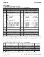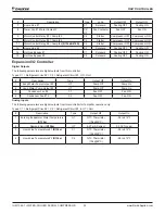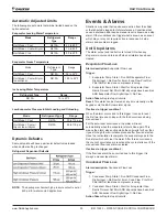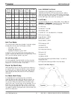
IOM 1322-1 • WATER-COOLED SCROLL COMPRESSOR 28 www.DaikinApplied.com
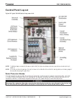
Control Panel Layout
Figure 19: Typical Control Panel, 4-Compressor Unit
NOTE:
1. Additional space provided in the upper right section for optional multiple point power connection and optional circuit
breakers.
NOTE:
2. Front door has a slot opening at the top for access to the MicroTech II controller for viewing display and making keypad
entries without opening the panel door.
Motor Protection Module
The motor protection system consists of an external control module, located on each compressor, motor terminal box, connected
to a series of thermistors located in the motor windings and the compressor discharge port. If the windings experience an over-
temperature condition or the discharge temperature is excessive, the module will trip and shut off the compressor.
WARNING
Disconnect the compressor three-phase power before removing the terminal box cover Removal of the terminal box
cover will expose the three-phase power connections . Contact with them can cause serious injury or death .
Unit Configuration
Summary of Contents for IOM 1322-1
Page 4: ......
Page 57: ...Unit Controller Operation www DaikinApplied com 57 IOM 1322 1 WATER COOLED SCROLL COMPRESSOR...
Page 71: ...Unit Maintenance www DaikinApplied com 71 IOM 1322 1 WATER COOLED SCROLL COMPRESSOR...
Page 74: ...IOM 1322 1 WATER COOLED SCROLL COMPRESSOR 74 www DaikinApplied com Troubleshooting Chart...
Page 75: ...Troubleshooting Chart www DaikinApplied com 75 IOM 1322 1 WATER COOLED SCROLL COMPRESSOR...
Page 76: ...IOM 1322 1 WATER COOLED SCROLL COMPRESSOR 76 www DaikinApplied com Troubleshooting Chart...
Page 77: ...Troubleshooting Chart www DaikinApplied com 77 IOM 1322 1 WATER COOLED SCROLL COMPRESSOR...
Page 78: ...IOM 1322 1 WATER COOLED SCROLL COMPRESSOR 78 www DaikinApplied com Troubleshooting Chart...


