


English
1-5
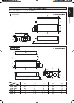
FWC02/03/04/05/06/08/10FD
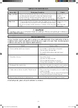
ELECTRICAL WIRING CONNECTION
IMPORTANT:
* These values are for information only. They should be checked and selected to comply with local and/or
national codes and/or national codes and regulations. They are also subject to the type of installation and
size of conductors.
** The appropriate voltage range should be checked with label data on the unit.
A main switch or other means for disconnection, having a contact separation in all poles, must be incorporated
in the fixed wiring in accordance with the relevant local and national legislation.
Note:
This is a proposed wiring connection. It may change subject to the chiller unit and must comply with the local and national
code and regulations.
Model
Indoor
FWC02FD
FWC03FD
FWC04FD
FWC05FD
Voltage Range**
Indoor
220V-240V/ ~ /50Hz +
!
Power Supply Cable Size*
mm
2
Number of Conductors
1.5
5
1.5
5
1.5
5
1.5
5
Recommended Time Delay Fuse*
A
1
1
1
1
Model
Indoor
FWC06FD
FWC08FD
FWC10FD
Voltage Range**
Indoor
220V-240V/ ~ /50Hz +
!
Power Supply Cable Size*
mm
2
Number of Conductors
1.5
5
1.5
5
1.5
5
Recommended Time Delay Fuse*
A
2
2
3
FCU 1
FCU 2
FCU 3
FSC
X2
X1
Chiller
FL
FM
FH
N
!
There must be an all pole
disconnection in the supply mains
with a contact separation of at
least 3mm.
All power line must be from the
same phase.
TH
220-240V/~/50Hz or
208-230V/~/60Hz
TH
220-240V/~/50Hz or
208-230V/~/60Hz
220-240V/~/50Hz or
208-230V/~/60Hz
TH
FSC
FSC
FL
FM
FH
N
FL
FM
FH
N
L
N
L
N
L
N
FL
Fan Low
FM
Fan Medium
FH
Fan High
N
Neutral
FSC
Fan Speed Controller
X1, X2, X3
Relay (220~240V, 10A)
TH
Thermostat
X3
1 IM-CCFWD-0915(1)-DAIKIN-EN.ind5 5
1 IM-CCFWD-0915(1)-DAIKIN-EN.ind5 5
4/13/16 3:33:59 PM
4/13/16 3:33:59 PM