REMOVAL
PROCEDURE
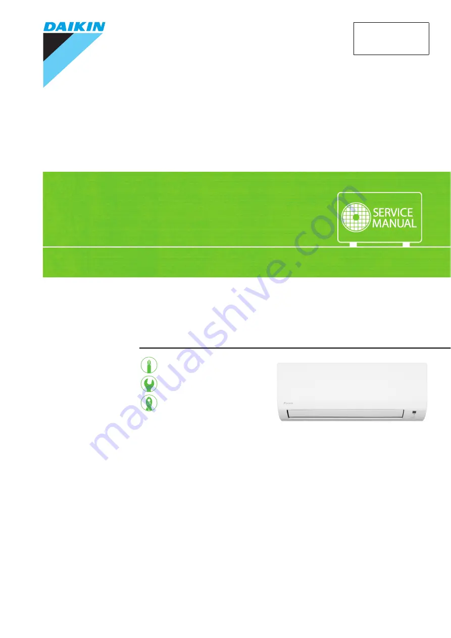
S E R V I C E M A N U A L
Indoor Unit
Inverter / Non-Inverter
Wall Mounted Type
1.5/2.0/2.5/3.5/4.2/5.0 kW Class9000/12000/15000/18000 Btu/h Class
Si041551EB
Page 1: ...REMOVAL PROCEDURE S E R V I C E M A N U A L Indoor Unit Inverter Non Inverter Wall Mounted Type 1 5 2 0 2 5 3 5 4 2 5 0 kW Class 9000 12000 15000 18000 Btu h Class Si041551EB...
Page 2: ...KC20QVM4 CTKM25PV14 CTKM35PV14 CTKM42PV14 CTKM50PV14 CTKM09PV2S CTKM12PV2S CTKM15PV2S CTKM18PV2S CTKS25QVM CTKS35QVM CTV25PV1G CTV35PV1G CTV50PV1G FTKC09QV2S FTKC12QV2S FTKC25QVM FTKC35QVM FTKC25QVM4...
Page 3: ...ters Front Panel 2 2 Front Grille 3 3 Horizontal Blade 4 4 Electrical Box 5 5 PCBs 8 6 Drain Pan Swing Motors Vertical Blade ASSYs 12 7 Indoor Heat Exchanger 16 8 Fan Rotor Fan Motor 18 Note The illus...
Page 4: ...ssembling insert the air filter along the guides Insert the air filter with the FRONT mark faced up Be sure to insert the 2 hooks when installing the air filter 1 2 Open the front panel Unfasten the 2...
Page 5: ...tep Procedure Points 1 Remove the 2 screws of the front grille 2 3 Unfasten the 3 hooks at the top Pull out the upper part of the front grille lift up the lower part and then remove the front grille T...
Page 6: ...while bending the horizontal blade slightly Reassembling procedure 1 Fit the horizontal blade to the right shaft first Make sure to rotate the horizontal blade so the shaft fits correctly 2 Fit the h...
Page 7: ...nfasten the hook and remove the wire fixture Remove the 4 screws of the terminal board and disconnect the connecting wire When reassembling be sure to fasten the hook before tightening the screw 2 Rem...
Page 8: ...varies depending on the model 4 Unfasten the 4 hooks and remove the electrical box cover When reassembling make sure that the 4 hooks are securely fastened 5 6 Disconnect the connector S6 Release the...
Page 9: ...he harnesses from the 5 hooks S200 fan motor 11 12 Remove the screw of the electrical box Slightly lift the electrical box upward and remove it When reassembling make sure to fasten the hook at the fr...
Page 10: ...eiver PCB 1 2 Remove the connector S26 Release the harnesses from the 3 hooks and the slit 3 Disconnect all the 5 terminals 4 Release the earth ground wire yellow green from the slit and the groove S2...
Page 11: ...oks 7 Remove the connector S32 and release the harness from the slit S32 thermistor 8 Unfasten the 4 hooks and remove the control PCB When reassembling be sure to fit the control PCB to the 4 projecti...
Page 12: ...of the display signal receiver unit 2 Release the harness of the display signal receiver unit from the hook 3 Release the harness from the hook The INTELLIGENT EYE sensor PCB can be removed without di...
Page 13: ...the display signal receiver PCB 1 Release the harness from the slit and the 3 hooks 2 Turn over the PCB ASSY unfasten the 3 hooks and remove the display signal receiver PCB Step Procedure Points Hook...
Page 14: ...Step Procedure Points 1 Remove the drain pan Use a short screwdriver from the back 1 Lift up the indoor unit and remove the screw 2 Disconnect the drain hose Hold the indoor unit up with a piece of w...
Page 15: ...n the swing motor for horizontal blade 3 Remove the swing motor for vertical blades Some models do not have the swing motor for vertical blades 1 Remove the 2 screws 2 Release the shaft of the vertica...
Page 16: ...models Each vertical blade ASSY has 5 fins It is impossible to replace only one fin The vertical blade ASSY is not marked for difference between right and left 1 2 3 Unfasten the 3 hooks of the vertic...
Page 17: ...ible to replace only one fin The vertical blade ASSY is not marked for difference between right and left 1 Unfasten the upper 2 hooks 2 3 4 Unfasten the 3 hooks at the shaft mounting part by pressing...
Page 18: ...g then collect all refrigerant from the unit After conducting vacuum drying recharge proper amount of refrigerant From the viewpoint of global environmental protection make sure to use a vacuum pump f...
Page 19: ...g 4 Remove the 2 screws on the left side and unfasten the hook on the rear side 5 Unfasten the 2 hooks on the right side and lift up the indoor heat exchanger Step Procedure Points Hook Piping fixture...
Page 20: ...supplies before disassembling work Step Procedure Points 1 Remove the screw of the right side plate 2 Unfasten the 2 hooks and remove the right side plate 3 Remove the fan rotor fan motor When reassem...
Page 21: ...nd remove the fan motor stator ASSY from the fan rotor Unfasten the 2 hooks of the fan motor stator ASSY 6 Disassemble the fan motor stator ASSY Step Procedure Points Hook Fan motor stator ASSY R23507...
Page 22: ...Month Year Version Revised contents 07 2015 Si041551E First edition 05 2016 Si041551EA Model addition FTKC09 12QV2S FTKC25 35QVM FTKC25 35QVM4 FTKC25 35QVMV 12 2016 Si041551EB Model addition CTKC15 20...
Page 23: ...ies supplied or specified by Daikin Ask a qualified installer or contractor to install those parts and accessories Use of unauthorised parts and accessories or improper installation of parts and acces...