


7 Installation
Installation manual
20
EZESHP20 EZLSHP20AUAW1B
Exigo E1500 Trailer Refrigeration Unit
4P726857-1 – 2023.03
1
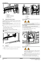
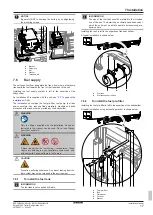
Plug the 2 pin connector (a) of the connection cable in the
socket (b) of the fuel pump cable.
a b
c
a
2 pin connector of the connection cable
b
Socket of the fuel pump cable
c
Fuel pump
2
Guide electrical connection cable (d) towards the front of the
trailer.
3
Attach the cable to the trailer undercarriage.
d
b
e
a
f
c
a
2 pin connector of the connection cable
b
Socket of the fuel pump cable
c
Fuel pump
d
Connection cable
e
Two pin connector of the connection cable
f
Socket of the unit cable
4
Plug the 2 pin connector (e) of the connection cable in the
socket (f) of the unit cable.
e f
e
2 pin connector of the connection cable
f
Socket of the unit cable
The fuel pump cable coming out of the unit is labelled "Fuel pump".
The fuel pump is connected to the X50Y connector.
FUEL PUMP
0B
AT
76
1
2
X50Y
BN
2x1.5²
W25
BU
BN
2x1.5²
W25
7.7
To install the Iot module
a
a
IoT module
1
Install the Iot module (a).
2
Plug the 2 pin connector of the connection cable in the socket
of the unit cable.
The Iot module is connected to the X7Y connector.
7.8
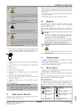
To install the door micro switch
INFORMATION
When the cold room door is closed, a micro switch (NO
contact) sends a signal to the unit.
The micro switch signal has a dual function. As soon as the cold
room door opens, it interrupts the thermoregulation mode and
switches on the internal lighting in the cold room.
a
a
Rear door switch
1
Install the door micro switch (a) so that it gives a signal when
the door is closed.
2
Guide the electrical cable from the switch to the unit.
3
Plug the 2 pin connector (c) of the connection cable in the
socket (b) of the unit cable.


