


D
–EIMHP01201-18_04EN - 19/24
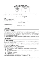
Table 1 - Table 1 of EN60204-1 Point 5.2
Section of the copper
phase conductors
feeding
the equipment
S
[mm
2
]
Minimum cross-section
of the external copper
protection conductor
S
p [mm
2
]
S
≤ 16
16 <
S
≤ 35
S
> 35
S
16
S
/2
3.11.3
Phase unbalance
In a three-phase system, the excessive imbalance between the phases is the cause of the engine overheating. The
maximum permitted voltage unbalance is 3%, calculated as follows:
𝑆𝑏𝑖𝑙𝑎𝑛𝑐𝑖𝑎𝑚𝑒𝑛𝑡𝑜 % =
(𝑉𝑥 − 𝑉𝑚) ∗ 100
𝑉𝑚
where:
Vx = phase with greater unbalance
Vm = average of the tensions
Example: the three phases measure 383, 386 and 392 V respectively. The average is:
383 + 386 + 392
3
= 387 𝑉
The unbalance percentage is:
(392 − 387) ∗ 100
387
= 𝟏. 𝟐𝟗 %
less than the maximum allowed (3%).
4
OPERATION
4.1
Operator’s responsibilities
It is essential that the operator is appropriately trained and becomes familiar with the system before operating the unit. In
addition to reading this manual, the operator must study the microprocessor operating manual and the wiring diagram in
order to understand start-up sequence, operation, shutdown sequence and operation of all the safety devices.
During the unit’s initial start-up phase, a technician authorized by the manufacturer is available to answer any questions
and to give instructions as to the correct operating procedures.
The operator must keep a record of operating data for every installed unit. Another record should also be kept of all the
periodical maintenance and servicing activities.
If the operator notes abnormal or unusual operating conditions, he is advised to consult the technical service authorized
by the manufacturer.
5
MAINTENANCE
5.1
Routine maintenance
This unit must be maintained by qualified technicians. Before beginning any work on the system the personnel shall assure
that all security precautions have been taken.
Neglecting unit maintenance in these environments, could degrade all parts of the units (coils, compressors, frames, pipes,
etc..) with negative effect on performances and functionality.
There are two different levels of maintenance, which can be chosen according to the type of application (critical/non critical)
or to the installation environment (highly aggressive).
Examples of critical applications are process cooling, data centres, etc.
Highly Aggressive Environments can be defined as the follows:
•
Industrial environment (with possible concentration of fumes result of combustion and chemical process)
•
Costal environment;
•
Highly polluted urban environment;
•
Rural environment close to of animal excrement and fertilizers, and high concentration of exhaust gas from diesel
generators.
•
Desert areas with risk of sandstorms;
•
Combinations of the above
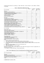
Table 2 lists all Maintenance activities for standard applications and standard environment.
Table 3 lists all Maintenance activities for critical applications or highly aggressive environment.


