Daikin EWYD-4Z B Installation, Operation And Maintenance Manual Download Page 17

D

–EIMHP01201-18_04EN - 17/24 
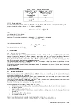
3.8 

Evaporator and condenser exchangers anti-freeze protection 

Evaporator and condenser are supplied with a thermostatically controlled anti-freeze electrical resistance, which provides 
adequate anti-freeze protection at temperatures as low as 

–16°C.  

However,  unless  the  heat  exchangers  are  completely  empty  and  cleaned  with  anti-freeze  solution,  additional  methods 
must also be used against freezing. 
Two or more of below protection methods shall be considered when designing the system as a whole: 


Continuous water flow circulation inside piping and exchangers 


Addition of an appropriate amount of glycol inside the water circuit 


Additional heat insulation and heating of exposed piping 


Emptying and cleaning of the heat exchanger during the winter season 

It is the responsibility of the installer and/or of local maintenance personnel to ensure that described anti-freeze methods 
are  used.  Make  sure  that  appropriate  anti-freeze  protection  is  maintained  at  all  times.  Failing  to  follow  the  instructions 
above could result in unit damage. Damage caused by freezing is not covered by the warranty. 
 

3.9 

Installing the flow switch 

To ensure sufficient water flow through the evaporator and condenser, it is essential that a flow switch be installed on both 
water circuits. The flow switch can be installed either on the inlet or outlet water piping. The purpose of the flow switch is 
to stop the unit in the event of interrupted water flow, thus protecting the evaporator and the condenser. 
The manufacturer offers, as optional, a flow switch that has been selected for this purpose. 
This paddle-type flow switch is suitable for heavy-

duty outdoor applications (IP67) and pipe diameters in the range of 1” to 

8

”. 

The  flow  switch  is  provided  with  a  clean  contact  which must  be  electrically  connected  to  terminals  shown  in  the  wiring 
diagram. Flow switch has to be tune to intervene when the evaporator and/or condenser water flow is lower than 50% of 
nominal flow rate. 
For  a  proper  unit  operation,  the  water  flow-rate  of  both  heat  exchangers  (evaporator  and  condenser)  must  always 
recirculate when the unit switch is active (On). 
  

Fig. 7 - Water piping connection 


1.  Pressure Gauge 
2.  Flexible connector 
3.  Flow switch 
4.  Temperature probe 

5.  Isolation Valve 
6.  Pump 
7.  Filter 

 
3.10 

Minimum system water volume (for Cold and Hot side) 

All cold and hot water systems need adequate time to react to a load change. In case of multipurpose unit, the machine 
follows the set-point on cold side as well as the se-point on hot side. The control of the heating and cooling capacity of 
the unit is achieved by managing the load of the compressors (with VFD) and by cycling each circuit independently 
between the following operating modes: cooling only, c heating, and heating only. The potential for short cycling 
usually exists when the cooling an

d heating loads falls below the minimum unit’s capacity or in systems with insufficient 

water volumes.  
Design considerations for systems water volume are the minimum cooling and heating load; the minimum cooling and 
heating unit’s capacity; the time for each circuit to perform the switch of operating mode; on heating side also the defrost 
effects needs to be considered. 
The water content is necessary to ensure the stability of plant operation and accurate temperature control. To determine 
the right value all the component of the systems should be considered as well as the plant layout and control strategy in 
place. 
Assuming that there are no sudden load changes and that the chiller plant has reasonable turndown, a rule of thumb of 
“6,5 litres per kW” is considered for comfort cooling and comfort heating application. The water content is calculated on 
the bases of the “6.5 lt/kW” rule, is intended as the useful water volume always flowing through both cold and hot heat 
exchangers.   
Note that in presence of any bypass that cause short circuit of the supply water with the return the resulting useful 
volume will be lower and lead to system instability.  

Summary of Contents for EWYD-4Z B

Page 1: ...ns REV 04 Date December 2019 Supersedes D EIMHP01201 18_03EN Multipurpose unit with Inverter Driven Single Screw Compressor EWYD 4ZB Refrigerant R 134a Installation Operation and Maintenance Manual D...

Page 2: ...connections 18 3 10 1 Cable requirements 18 3 10 2 Interconnection cables 18 3 10 3 Phase unbalance 19 4 OPERATION 19 Operator s responsibilities 19 5 MAINTENANCE 19 5 1 Routine maintenance 19 5 2 Uni...

Page 3: ...D EIMHP01201 18_04EN 3 24 Fig 1 Typical refrigerant circuit Water inlet and outlet are indicative Please refer to the machine dimensional diagrams for exact water connections...

Page 4: ...HEAT EXCHANGER COLD WATER 9 SHELL TUBE HEAT EXCHANGER HOT WATER 10 PRESSURE RELIEF VALVE Psat 24 5 bar CHANGEOVER DEVICE OPTIONAL 11 PRESSURE RELIEF VALVE Psat 15 5 bar CHANGEOVER DEVICE OPTIONAL 12...

Page 5: ...e electrical panel Single circuit unit Double circuits unit Label Identification 1 Manufacturer s logo 5 Cable tightening warning 2 Gas type 6 Non flammable gas symbol 3 Hazardous Voltage warning 7 Un...

Page 6: ...cuits close the section of the piping concerned and drain the fluid gradually to stabilise the pressure at the atmospheric level 12 do not use your hands to check possible refrigerant leaks 13 disable...

Page 7: ...our pressure from evaporation pressure to condensation pressure Evaporator where the low pressure liquid refrigerant evaporates to cool the water Condenser where the high pressure vapour refrigerant c...

Page 8: ...ntact factory for further details For operation with temperature at the outlet of the cold heat exchanger below 4 C the unit must operate with glycol mixture ethylene or propylene glycol The glycol pe...

Page 9: ...be able to operate outside the above envelope with compressors unloading Please contact factory for further details For operation with temperature at the outlet of the cold heat exchanger below 4 C th...

Page 10: ...ts around the unit 1 1 Noise The unit is a source of noise mainly due to rotation of compressors and fans The noise level for each model size is listed in sales documentation If the unit is correctly...

Page 11: ...ith 4 lifting points The drawing shows only the 6 fans version For the 4 fans version the lifting mode is the same Unit with 6 lifting points The drawing shows only the 12 fans version The lifting mod...

Page 12: ...D EIMHP01201 18_04EN 12 24 Unit with 8 lifting points...

Page 13: ...he condenser Limited installation space could reduce the normal air flow thus significantly reducing the machine s performance and considerably increasing consumption of electrical energy When decidin...

Page 14: ...mmended For further solutions please consult Daikin technicians The minimum distances reported above ensure functionality of the unit in most applications However there are specific situations which i...

Page 15: ...is working quite normally Fig 6 Multiple Chiller Installation In order to avoid the hot air recirculation due to dominant winds the installation where all units are aligned to the dominant wind is pre...

Page 16: ...as possible to the unit as in Fig 7 If the water filter is installed in another part of the water system the Installer has to guarantee the cleaning of the water pipes between the water filter and th...

Page 17: ...when the evaporator and or condenser water flow is lower than 50 of nominal flow rate For a proper unit operation the water flow rate of both heat exchangers evaporator and condenser must always recir...

Page 18: ...er harmonics such as an inverter or phase cut ground losses can increase to much higher values about 2 A The protections for the power supply system must be designed according to the values mentioned...

Page 19: ...g data for every installed unit Another record should also be kept of all the periodical maintenance and servicing activities If the operator notes abnormal or unusual operating conditions he is advis...

Page 20: ...nt leakage X Verify refrigerant flow using the liquid sight glass Sight glass full X Verify filter dryer pressure drop X Verify oil filter pressure drop Note 5 X Analyse compressor vibrations X Analys...

Page 21: ...it is necessary to wash periodically the frame surfaces with water and suitable detergents In case of part of unit frame paint came off it is important to stop its progressive deterioration by repain...

Page 22: ...nd its operating limits or not performing proper maintenance according to this manual can void the warranty Observe the following points in particular in order to conform to warranty limits 1 The unit...

Page 23: ...label supplied with the product as following instructions Any refrigerant charge for each circuit 1 2 3 added during commissioning the total refrigerant charge 1 2 3 calculate the greenhouse gas emis...

Page 24: ...nt and the products and services presented therein Specification are subject to change without prior notice Refer to the data communicated at the time of the order Daikin Applied Europe S p A explicit...

Reviews: