


D-EIMWC00908-16EN - 24/52
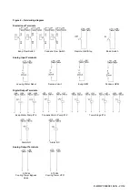
Field Wiring Diagram Notes
1.
Power wiring between the terminal box and compressor terminals is factory installed.
2.
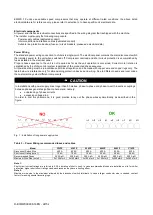
Voltage unbalance not to exceed 2% with a resultant current unbalance of 6 to 10 times the voltage unbalance. Standard. Supply
voltage must be +/- 10% of compressor nameplate voltage.
3.
A customer furnished 115 Vac power for alarm relay coil may be connected between MC115 terminals 519 power and 506 neutral
of the control panel. For normally open contacts wire between 518 and 519. For normally closed wire between 520 and 519. The
alarm is operator programmable. Maximum rating of the alarm relay coil is 25VA.
4.
Remote on/off control of unit can be accomplished by installing a set of dry contacts between MC24 terminals 710 and 703.
5.
Customer supplied 115 VAC 20 amp power for optional evaporator and condenser water pump control power and tower fans is
supplied to unit control terminals MC115 terminals 505 power and 506 neutral, PE equipment ground.
6.
Optional customer supplied 115 VAC, 25-VA maximum coil rated, chilled water pump relay (EP1 & 2) may be wired as shown. This
option will cycle the chilled water pump in response to chiller demand.
7.
The condenser water pump must cycle with the unit. A customer supplied 115 VAC 25 VA maximum coil rated, condenser water
pump relay (CP1 & 2) is to be wired as shown.
8.
Optional customer supplied 115 VAC 25 VA maximum coil rated cooling tower fan relays (C1 - C4 optional) may be wired as
shown. This option will cycle the cooling tower fans in order to maintain unit head pressure.
9.
Optional Control Inputs. The following 4-20 mA optional inputs are connected as shown on MC24 terminals:
Demand Limit; Terminals 716 and 704 common
Chilled Water Reset; Terminals 712 and 704 common
Evaporator Water Flow; Terminals 717 and 704 common
Condenser Water Flow; Terminals 718 and 704 common
10. Optional Control Power Source. 115 Volt control power can be supplied from a separate circuit and fused at 20 A inductive load.
Connection is to terminals 519 and 506 common on MC115.
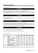
Control Wiring
The control circuit on the is designed for 115 V. Control power is supplied from a factory-wired transformer located in the
electrical box. Control wiring must be of suitable size in accordance with local regulations.
VFD Line Harmonics
Despite their many benefits, care must be taken when applying VFDs due to the effect of line harmonics on the building
electric system. VFDs cause distortion of the AC line because they are nonlinear loads, that is, they don't draw sinusoidal
current from the line. They draw their current from only the peaks of the AC line, thereby flattening the top of the voltage
waveform. Some other nonlinear loads are electronic ballasts and uninterruptible power supplies.
Line harmonics and their associated distortion can be critical to ac-drives for three reasons:
1. Current harmonics can cause additional heating to transformers, conductors, and switchgear.
2. Voltage harmonics upset the smooth voltage sinusoidal waveform.
3. High-frequency components of voltage distortion can interfere with signals transmitted on the AC line for some
control systems.
The harmonics of concern are the 5
th
, 7
th
, 11
th
, and 13
th
. Even harmonics, harmonics divisible by three, and high
magnitude harmonics are usually not a problem.
Current Harmonics
An increase in reactive impedance in front of the VFD helps reduce the harmonic currents. Reactive impedance can be
added in the following ways:
1. Mount the drive far from the source transformer.
2. Add line reactors. They are standard equipment on EWWD FZ chillers.
3. Use an isolation transformer.
4. Use a harmonic filter.
Voltage Harmonics
Voltage distortion is caused by the flow of harmonic currents through a source impedance. A reduction in source
impedance to the point of common coupling (PCC) will result in a reduction in voltage harmonics. This can be done in the
following ways:
1. Keep the PCC as far from the drives (close to the power source) as possible.
2. Increase the size (decrease the impedance) of the source transformer.
3. Increase the capacity (decrease the impedance) of the busway or cables from the source to the PCC.
4. Make sure that added reactance is "downstream" (closer to the VFD than the source) from the PCC.
Line Reactors
Five-percent line reactors are standard equipment on Magnitude chillers and located in each compressors power panel.
They are employed to improve the power factor by reducing the effects of harmonics.
Summary of Contents for EWWD320
Page 16: ...D EIMWC00908 16EN 16 52 Figure 4 Evaporator pressure drop...
Page 17: ...D EIMWC00908 16EN 17 52...
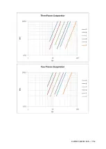
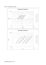
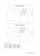
Page 18: ...D EIMWC00908 16EN 18 52 Figure 5 Condenser pressure drop...
Page 34: ...D EIMWC00908 16EN 34 52 Figure 12 Compressor overview...
Page 50: ...D EIMWC00908 16EN 50 52...
Page 51: ...D EIMWC00908 16EN 51 52...


