background image

D-EIMWC01008-16EU - 14/20 

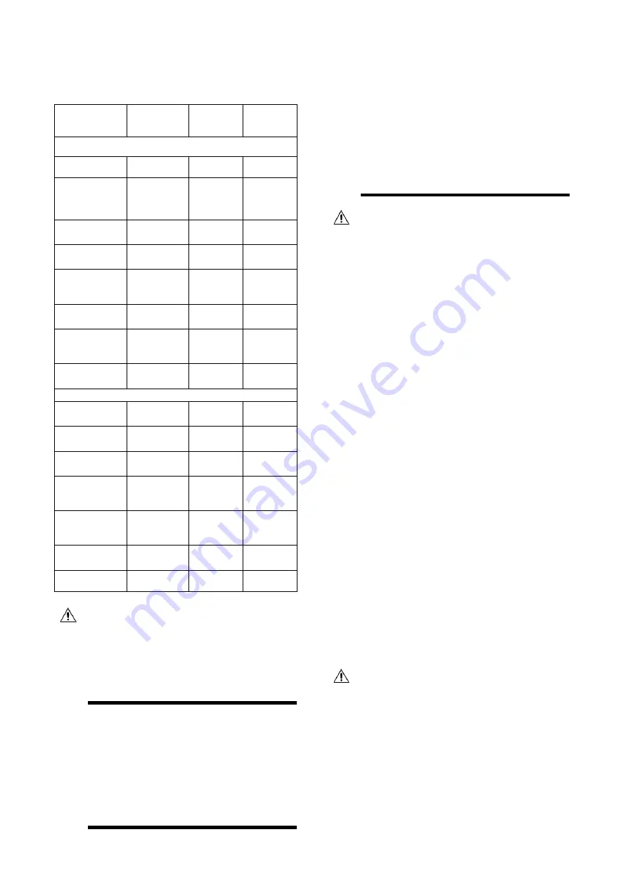
The water quality must be in accordance with the   
specifications listed the table below: 


Circulating 

water 

Supply 

water 

Tendency 

if out of 

criteria 

Items to be controlled


pH       at 25°C 

  6.8~8.0 

  6.8~8.0 

co

scale 

Electrical 
conductivity 
[mS/m] at 
25°C 

<40 

<30 

co

scale


Chloride Ion  
[mg Cl˜/l] 

<50 

<50 

corrosion 

Sulfate Ion 

[mg SO

4

²

˜/l] 

<50 

<50 

corrosion 

M-alcalinity 
(pH4.8) 

[mg CaCO

3

/l] 

<50 

<50 

  scale 

Total hardness 

[mg CaCO

3

/l] 

<70 

<70 

scale 

Calcium 
hardness 

[mg CaCO

3

/l] 

<50 

<50 

scale 

Silica Ion 

[mg SiO

2

/l] 

<30 

<30 

scale 

Items to be referred to 

Iron      

[mg Fe/l] 

<1,0 

<0,3 

co

scale


Copper  

[mg Cu/l] 

<1,0 

<0,1 

corrosion 

Sulfide Ion 

[mg S²

˜/l] 

not 

detectable 

not 

detectable 

 corrosion 

Ammonium 
Ion 

[mg NH

4

+/l] 

<1,0 

     <0,1 

 corrosion 

Remaining 
chloride 

[mg Cl/l] 


     <0,3 


     <0,3 

 corrosion 

Free carbide 

[mg CO

2

/l] 

     <4,0 

<4,0 

 corrosion 

Stability index 

co

scale


 The water pressure should not exceed the maximum  

        working pressure of 10 bar. 

NOTE         

Provide adequate safeguards in the water circuit to


make sure that the water pressure will never  


exceed the maximum allowable working  

                   pressure. 
 

13.  PIPING INSULATION 


The  complete  water  circuit,  inclusive  all  piping,  must  be 
insulated to prevent condensation and reduction of the cooling 
capacity. 
Protect  the  water  piping  against  water  freezing  during  winter 
period (e.g. by using a glycol solution or heatertape). 


14.  DISCHARGE FROM PRESSURE 

RELIEF DEVICES 

 
Discharge of the refrigerant into installation area has to be in 
accordance  with  local  regulations.  If  required it  is  possible to 
connect  a  1”  pipe  to  each  pressure  relef  valve  on  the 
condenser  and   

½” pipe to each pressure relief valve on the 

evaporator. 
Cross  section  and  length  of  the  discharge  line  must  comply 
with local codes. 


15.  FIELD WIRING 


 All field wiring and components must be installed by a  

        licensed electrician and must compy with relevant  
        European and national regulations 

        The field wiring must be carried out in accordance with 
         the wiring diagram supplied with the unit and the 


instructions given below. 

 
         Be sure to use a dedicated power circuit. Never use a  
         power supply shared by another appliance. 
 

NOTE   

Verify on the wiring diagram all electrical actions  

             mentioned below, in order to understand the operation  
             of the unit more deeply. 


15.1.  Parts table 


F1,2

……………………..Main fuses for the unit 

L1, 2, 3………………….Main supply terminals 
PE……………………… Main earth terminal 
S6

S……………………..Setpoint override 

FS……………………… Flowswitch 
Q10……………………..Main isolator switch 
---

………………………..Field wiring 


15.2.  Power circuit and cable 

requirements 

 
1      

The electrical power supply to the unit should be   


arranged so


that it can be switched on or off  

        independently


of the electrical supply to other  

        items of the plant and equipment in general. 
 

2      

A power circuit must be provided for connection of 

        the unit. This circuit must be protected with the  
        required


safety devices, i.e. a circuit breaker, a  

        slow blow fuse on each phase and an earth


leak  

        detector. Recommended fuses are mentioned on  
        the


wiring diagram supplied with the unit.


 Switch off the main isolator switvch before making any 

        connections (switch off the circuit breaker, remove or 
        switch off the fuses). 


15.3.  Connection of the watercooled 

water chiller power supply 


Using the appropriate cable, connect the power 
circuit to the L1, L2 and L3 terminals of the unit. 

2     

Connect the earth conductor (yellow/green) to the   

       earthing terminal PE. 


Summary of Contents for EWWD J Series

Page 1: ... water cooled screw chillers EWLD110J SS EWLD265J SS EWLH 80J SS EWLH190J SS EWLS 110J SS EWLS270J SS Refrigerant R 134a R1234ze R513A English 2 Deutsch 13 Français 25 Nederlands 36 Español 48 Italiano 60 Ελληνικά 72 Português 84 Русский 96 Swedish 107 Norsk 118 Finnish Suomi 129 Polski 140 Čech 152 Hrvat 163 Magyar 174 Român 185 Slovenski 196 Български 207 Slovenský 219 Installation Operation and...

Page 2: ...d to replace such personnel EWWD120J SS 280J SS EWWH090J SS 200J SS EWWS120J SS 270J SS EWLD 110J SS 265J SS EWLH 80J SS 190J SS EWLS 110J SS 270J SS Label Identification 1 Unit nameplate data 5 Manufacturer s logo 2 Lifting instructions 6 Emergency stop 3 Hazardous Voltage warning 7 Non flammable gas symbol 4 Electrical hazard symbol 8 Gas type ...

Page 3: ...R1234ZE 9 8 5 ADDITIONAL GUIDELINES FOR SAFE USE OF R1234ZE E FOR EQUIPMENT LOCATED IN THE OPEN AIR 9 8 6 ADDITIONAL GUIDELINES FOR SAFE USE OF R1234ZE E FOR EQUIPMENT LOCATED IN A MACHINERY ROOM 9 9 MAINTENANCE 10 9 1 ROUTINE MAINTENANCE FOR R1234ZE 10 10 EWLD J EWLH AND EWLS VERSIONS 11 10 1 PRECAUTIONS WHEN HANDLING PIPING 11 10 2 LEAK TEST AND VACUUM DRYING 11 10 3 CHARGING THE UNIT 11 11 PREP...

Page 4: ...OPER INSTALLATION OR ATTACHEMENT OF EQUIPMENT OR ACCESSORIES COULD RESULT IN ELECTRIC SHOCK SHORT CIRCUIT LEAKS FIRE OR OTHER DAMAGE TO THE EQUIPMENT BE SURE ONLY TO USE ACCESSORIES MADE BY DAIKIN WHICH ARE SPECIFICALLY DESIGNED FOR USE WITH THE EQUIPMENT AND HAVE THEM INSTALLED BY A PROFESSIONAL IF UNSURE OF INSTALLATION PROCEDURES OR USE ALWAYS CONTACT YOUR DAIKIN DEALER FOR ADVICE AND INFORMATI...

Page 5: ... 1600 1607 Operation weight Kg 1663 1675 Connections Chilled water inlet outlet 2 inch 3 Condenser water inlet outlet 2 inch 4 2 Victaulic coupling Model EWLD J 110 130 145 165 195 Dimensions HxWxL mm 1020x913x2726 Weight Unit weight Kg 1086 1101 1169 1164 1236 Operation weight Kg 1090 1114 1183 1183 1263 Connections Chilled water inlet outlet 2 inch 3 Liquid line inlet connection 3 inch 1 3 8 Gas...

Page 6: ...tion with Glycol Fixed minimum capacity at 100 2 Operation with Glycol below 4 C Evap LWT 3 Some units could work partialized in this area EWWH J EWLH J 1 Operation with Glycol Fixed minimum capacity at 100 2 Operation with Glycol below 4 C Evap LWT 3 Operation with fixed minimum capacity at 100 EWWS J EWLS J 1 Operation with Glycol below 4 C Evap LWT 2 Some units could work partialized in this ar...

Page 7: ...ling in the unit to a minimum It drilling is impreventable remove the iron filling thoroughly in order to prevent surface rust 6 UNPACKING AND PLACING THE UNIT 1 Remove the wooden beams from the unit 2 Install vibration mountings in case of an installation where noise and vibration might an impediment 3 Set the unit on a solid and level foundation The unit should be installed on a solid base It is...

Page 8: ...21 66 19 33 10 2 01 9 4 01 29 7 27 48 12 53 67 19 78 9 2 09 10 4 15 30 7 48 49 12 85 68 20 23 8 2 17 11 4 29 31 7 70 50 13 18 69 20 69 7 2 26 12 4 43 32 7 92 51 13 51 70 21 16 6 2 34 13 4 58 33 8 15 52 13 85 71 21 64 5 2 43 14 4 73 34 8 39 53 14 20 72 22 13 4 2 53 15 4 88 35 8 63 54 14 55 73 22 62 3 2 62 16 5 04 36 8 87 55 14 91 74 23 12 2 2 72 17 5 20 37 9 12 56 15 28 75 23 63 1 2 82 18 5 37 38 9...

Page 9: ...mity with the directives along with the documentation Before machine installation and commissioning the people involved in this activity must have acquired the information necessary to carry out these tasks applying all the information collected in this book Do not allow unauthorized and or unskilled personnel to access the unit The chiller has to be installed in open air or machinery room locatio...

Page 10: ...be done with due consideration of local airflow patterns accounting for location sources of ventilation and louvers Consideration shall also be given to the possibility of mechanical damage or contamination At least one detector shall be installed in each machinery room or the occupied space being considered and or at the lowest underground room for refrigerants heavier than air and at the highest...

Page 11: ... technicians Before beginning any work on the system the personnel shall assure that all security precautions have been taken Always protect the operating personnel with personal protective equipment appropriate for the tasks to be performed Common individual devices are Helmet goggles gloves caps safety shoes Additional individual and group protective equipment should be adopted after an adequate...

Page 12: ...h the product NOTE Take care for contamination of the remote condenser In order to avoid blocking of the system It is impossible for the manufacturer to control the contamination of the foreign condenser of the installer The unit has a strict contamination level 11 PREPARING CHECKING AND CONNECTING THE WATER CIRCUIT The units are equipped with a water inlet and water outlet for connection to a chi...

Page 13: ...ransmitting vibration and noise 6 For units in double circuit configuration with common leaving water control ELWT be sure to foresee an insertion hole for the additional water temperature sensor Sensor and sensor holder are optional parts The insertion hole shall be 1 4 GAS female thread and should be located in the mixed waterflow of the chillers Make sure that the sensortip is in the waterflow ...

Page 14: ...e relef valve on the condenser and pipe to each pressure relief valve on the evaporator Cross section and length of the discharge line must comply with local codes 15 FIELD WIRING All field wiring and components must be installed by a licensed electrician and must compy with relevant European and national regulations The field wiring must be carried out in accordance with the wiring diagram suppli...

Page 15: ... sent to specific refuse collection centres Oil must be collected and sent to specific refuse collection centres 16 BEFORE STARTING The unit should not be started not even for a very short period of time before the following pre commissioning checklist is filled out completely tick when checked standard steps to go through before starting the unit 1 Check for external damage 2 Open all shut off va...

Page 16: ...mp VFD D L Demand Limit DI Digital Inputs DO Digital Outputs DPS Double Set Point EF Esternal Fault EFS Evaporator Flow Switch EFS 1 Evaporator Flow Switch 1 EFS 2 Evaporator Flow Switch 2 GA General Alarm KPC Condensator Water Pump KPE 1 Evaporator Water Pump 1 KPE 2 Evaporator Water Pump 2 PS Power Supply Q10 Main Switch S O Setpoint Override TW1 Tower 1 Fan Step TW2 Tower 2 Fan Step TW3 Tower 3...

Page 17: ...D EIMWC01006 11EU 17 20 17 FACTORY AND FIELD CHARGED UNITS INSTRUCTIONS Errore Non si possono creare oggetti dalla modifica di codici di campo 18 FIELD CHARGED UNITS INSTRUCTIONS ...

Page 18: ...frigerant charge Factory Field h Greenhouse gas emission of the total refrigerant charge expressed as tonnes of CO2 equivalent m Refrigerant type n GWP Global Warming Potential p Unit serial number 2 The filled out label must be adhered inside the electrical panel Periodical inspections for refrigerant leaks may be required depending on European or local legislation Please contact your local deale...

Page 19: ... of its content and the products and services presented therein Specification are subject to change without prior notice Refer to the data communicated at the time of the order Daikin Applied Europe S p A explicitly rejects any liability for any direct or indirect damage in the broadest sense arising from or related to the use and or interpretation of this publication All content is copyrighted by...

Page 20: ...D EIMWC01006 11EU 20 20 ...

Reviews: