Daikin EWLD-J Installation, Operation And Maintenance Manual Download Page 32


D-EIMWC01008-16_03EN - 32/35 

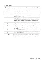
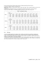
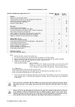
Standard Routine Maintenance Plan 


Routine maintenance programme 

(Note 2)


Weekly 

Monthly 

(Note 1)


Yearly 

(Note 2)


General 


Reading of operating data (Note 3) 


Visual inspection of machine for any damage and/or loosening  


Verification of thermal insulation integrity 


Clean and paint where necessary 


Analysis of water (Note 5) 


Electrical:


Verification of control sequence 


Verify contactor wear 

– Replace if necessary 


Verify that all electrical terminals are tight 

– Tighten if necessary 


Clean inside the electrical control board 


Visual inspection of components for any signs of overheating  


Verify operation of compressor and electrical resistance 


Measure compressor motor insulation using the Megger 


Refrigeration circuit:


Check for any refrigerant leakage 


Verify refrigerant flow using the liquid sight glass 

– Sight glass full 


Verify filter dryer pressure drop 


Verify oil filter pressure drop (Note 4) 


Analyse compressor vibrations 


Analyse compressor oil acidity (Note 6) 


Check safety valves (Note 7) 


Condenser section:


Clean the exchangers (Note 8) 


Notes: 

1.  Monthly activities include all the weekly ones 
2.  The annual (or early season) activities include all weekly and monthly activities 
3.  Machine operating values should be read on a daily basis thus keeping high observation standards  
4.  Replace the oil filter when the pressure drop across it reaches 2.0 bar  
5.  Check for any dissolved metals 

TAN (Total Acid Number) :  

0.10 : No action 

Between  0.10  and  0.19  :  Replace  anti-acid  filters  and  re-check  after  1000 
running hours. Continue to replace filters until the TAN is lower than 0.10.  

0.19 : Change oil, replace oil filter and filter dryer. Verify at regular intervals. 

6.  Safety valves 
Check that the lid and seal have not been tampered with.  


  Check that the discharge socket of the safety valves is not obstructed by any objects, rust or ice.    
  Check the manufacturing date shown on the safety valve. 


7.  Clean the pipes of the exchanger mechanically and chemically if the following occur: drop in the condenser 

water  capacity,  drop  in  the  differential  temperature  between  inlet  and  outlet  water,  high  temperature 
condensation


This unit, whether with R134a, R513A or R1234ze, must be maintained by qualified technicians. Before 
beginning any  work  on  the system,  personnel shall  assure  that all security precautions  have  been 
taken. 


Always protect the operating personnel with personal protective equipment appropriate for the tasks 
to  be  performed.  Common  individual  devices  are:  Helmet,  goggles,  gloves,  caps,  safety  shoes. 
Additional individual and group protective equipment should be adopted after an adequate analysis 
of the specific risks in the area of relevance, according to the activities to be performed.  


Summary of Contents for EWLD-J

Page 1: ...structions REV 03 Date 04 2021 Supersedes D EIMWC01008 16_02EU Installation Operation and Maintenance Manual EWWD EWLD J EWWH EWLH J EWWS EWLS J Installation Operation and Maintenance Manual D EIMWC01...

Page 2: ...GUIDELINES FOR REMOTE CONDENSER APPLICATION EWLD J EWLH and EWLS versions 22 6 1 Installation information for condenserless units 22 6 1 1 Precautions when handling piping 22 6 1 2 Leak test and vacu...

Page 3: ...alve Condenser Shut off valve Filter drier Shut off valve charge valve Solenoid valve Liquid indicator 1 2 3 4 5 6 7 8 Control equipment High Pressure Switch 21 0bar Pressure Transducer Temperature Tr...

Page 4: ...EWLH80J SS 190J SS EWLS110J SS 270J SS Label Identification Figure 2 Description of the labels applied to the electrical panel 1 Unit nameplate data 5 Manufacturer s logo 2 Lifting instructions 6 Eme...

Page 5: ...el 14 check that the unit has been grounded correctly before starting it 15 install the machine in a suitable area in particular do not install it outdoors if it is intended for use indoors 16 do not...

Page 6: ...sfers heat to the water An expansion valve which allows the pressure of condensed liquid refrigerant to be reduced from condensation pressure to evaporation pressure A water cooled evaporator where th...

Page 7: ...9 31 7 70 50 13 18 69 20 69 7 2 26 12 4 43 32 7 92 51 13 51 70 21 16 6 2 34 13 4 58 33 8 15 52 13 85 71 21 64 5 2 43 14 4 73 34 8 39 53 14 20 72 22 13 4 2 53 15 4 88 35 8 63 54 14 55 73 22 62 3 2 62 1...

Page 8: ...a and R513A According to the standard EN 378 1 2016 any refrigerant system that contains R134a or R513A can be installed without any restriction in open air or machinery rooms Anyway the building owne...

Page 9: ...and including the charge and safety classification of the refrigerant used shall be conducted to determine whether it is necessary to place the refrigerating system in a separate refrigeration machine...

Page 10: ...gerants heavier than air and at the highest point for refrigerants lighter than air Detectors shall be continuously monitored for functioning In the case of a detector failure the emergency sequence s...

Page 11: ...ndensing atmosphere may damage electronic components 4 2 Operation The Daikin EWWD J EWLD J EWWH J EWLH J EWWS J EWLS J packaged water cooled water chillers are designed for indoor installation and us...

Page 12: ...D EIMWC01008 16_03EN 12 35 4 2 2 Operation range EWWD J 1 Operation with Glycol below 4 C Evap LWT EWLD J 1 Operation with Glycol below 4 C Evap LWT...

Page 13: ...vap LWT 2 Option111 and operation with Glycol below 4 C Evap LWT 3 Option111 4 Option 111 Option 189 5 Option 189 EWLH J 1 Operation with Glycol below 4 C Evap LWT 2 Option111 and operation with Glyco...

Page 14: ...D EIMWC01008 16_03EN 14 35 EWWS J 1 Operation with Glycol below 4 C Evap LWT EWLS J 1 Operation with Glycol below 4 C Evap LWT...

Page 15: ...re 3 Lifting When handling the unit take into account the following 1 List the unit preferably with a crane and belts in accordance with the instructions on the unit The length of the ropes 1 to be us...

Page 16: ...x the unit on a concrete base with anchor bolts 1 Anchor bolt 2 Washer 3 Rubber plate 4 Row cork or rubber sheet 5 Ground 6 Concrete floor 7 Ditch Figure 4 Unit Levelling Fix anchor bolts into the con...

Page 17: ...antee the cleaning of the water pipes between the water filter and the BPHE Recommended maximum opening for strainer mesh is 0 87 mm DX S T 1 0 mm BPHE 1 2 mm Flooded Precautions for correct use 9 BPH...

Page 18: ...ection pipes prior the operation see figure Connecting the filter The filter kit supplied with the unit must be installed in front of the evaporator water inlet by means of the supplied Victaulic coup...

Page 19: ...nge as specified in the table below and a minimum water volume is required in the system Model Minimum water flow l min Maximum water flow l min EWWD120J EWLD110J EWWH090J EWLH080J EWWS120J EWLS110J 1...

Page 20: ...anti freeze electrical resistance which provides adequate anti freeze protection at temperatures as low as 18 C However unless the heat exchangers are completely empty and cleaned with anti freeze so...

Page 21: ...gram terminals L1 L2 and L3 5 Supply water to the evaporator and verify if waterflow is within the limits as given in the table under Water charge flow and quality 6 The piping must be completely purg...

Page 22: ...e used For copper to copper joints use a phos copper solder with 6 to 8 silver content A high silver content brazing rod must be used for copper to brass or copper to steel joints Only use oxy acetyle...

Page 23: ...must be between 3 and 8 K c Verify the oil sight glass Level must be within the sight glass d Verify the liquid line sight glass It should be sealed and not indicate moisture in the refrigerant e As l...

Page 24: ...D EIMWC01008 16_03EN 24 35 Figure 5 Condenser located with no elevation difference Figure 6 Condenser located above the unit...

Page 25: ...alves etc Table 2 shows the equivalent length of pipe for various nonferrous valves and fittings Follow these steps when calculating line size 1 Start with an initial approximation of equivalent lengt...

Page 26: ...oling may be affected In these situations insulate the liquid lines Reference for liquid line sizing is shown in Table 3 It has to be used for reference only for circuit working with condensing temper...

Page 27: ...234ze R513A 6 2 4 Oil charge In remote condenser application the oil charge into the compressor has to take into account that a percentage of oil around 1 is usually mixed into the refrigerant so some...

Page 28: ...dards for industrial environments Therefore it is not intended for use in residential areas e g installations where the product is connected to a low voltage public distribution system Should this pro...

Page 29: ...al areas e g installations where the product is connected to a low voltage public distribution system Should this product need to be connected to a low voltage public distribution system specific addi...

Page 30: ...operating manual and the wiring diagram in order to understand start up sequence operation shutdown sequence and operation of all the safety devices During the unit s initial start up phase a technici...

Page 31: ...sure that the work area is properly ventilated before working on the refrigerant circuit or before welding brazing or soldering work ensure that the leak detection equipment being used is non sparking...

Page 32: ...be read on a daily basis thus keeping high observation standards 4 Replace the oil filter when the pressure drop across it reaches 2 0 bar 5 Check for any dissolved metals TAN Total Acid Number 0 10...

Page 33: ...unbalance between phases exceeding 3 The unit must stay turned off until the electrical problem has been solved 4 No safety device either mechanical electrical or electronic must be disabled or overri...

Page 34: ...ed inside the electrical panel Fill in with indelible ink the refrigerant charge label supplied with the product as following instructions Any refrigerant charge for each circuit 1 2 3 added during co...

Page 35: ...e of its content and the products and services presented therein Specification are subject to change without prior notice Refer to the data communicated at the time of the order Daikin Applied Europe...

Reviews: