


EWAQ080~260DAYN
Packaged air-cooled water chillers
4PW35556-1E
Operation manual
28
_÷ C2 ACT. PRESSURES
HP2:019$0b = 050$8¢
LP2:004$4b = -05$2¢
FAN2:OFF
_÷ EXTRA READOUT
C11RH:00000hCS:00000
RHP1:00001hP2:00000h
_÷ EXTRA READOUT
CURRENT:055A
VOLTAGE:023V
_ TIME AND DATE
TIME: 22h35
DATE FORMAT:DD/MM/YY
DATE: WED 24/01/07
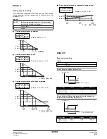
_ FREE COOLING
MODE:AMBIENT
SP: 05$0¢ DIF:01$0¢
PUMP:ON LEAD:000s
_ MASTER SETTINGS
MODE:NORMAL
OFFSET:0000h
PUMP ON IF:UNIT ON
_v ADVANCED
PASSWORD NEEDED FOR:
SETPOINT MENU:Y
UNIT ON/OFF:Y
_÷ ADVANCED
MAIN MENU:GRAPHIC
LOGOUT TIMER :05min
BUZZER IF SAFETY:YES
_^ ADVANCED
BACKLIGHT TIME:05min
GRAPHIC READOUT:YES
ENTER SERVICE
PASSWORD: 0000
TO LOGIN
_÷ COMP. OUTPUTS
C11:ON C12:ON
C21:ON C22:ON
_÷CHANG. INP/OUTPUTS
DO6 NONE (OPEN)
AI1 NONE
AI2 NONE
_÷CHANG. INP/OUTPUTS
AI3 NONE
AI4 NONE
AO1 NONE
SERVICE MENU
ADVANCED
DEFROST
DICN
FREE COOLING
TIME AND DATE
_^ COMMUNICATION
RS232 ONLINE:N
RS485 ONLINE:N
DIII ONLINE:N
_÷ FAN INP/OUTPUTS
C1 FANSTEP 1:CLOSED
C1 FANSTEP 2:CLOSED
C1 FANSTEP 3:CLOSED
_÷ FAN INP/OUTPUTS
C2 FANSTEP 1:CLOSED
C2 FANSTEP 2:CLOSED
C2 FANSTEP 3:CLOSED
_÷CHANG. DIG. INPUTS
DI4 NONE
DO1 W.(NO) :O
DO2 GEN.OPERATION :O
_÷CHANG. DIG. INPUTS
DI1 NONE
DI2 NONE
DI3 NONE
_÷CHANG. INP/OUTPUTS
DO3 NONE (OPEN)
DO4 NONE (OPEN)
DO5 NONE (OPEN)
_÷ UNIT STATUS
C11:OFF SAFETY ACT.
C12:OFF SAFETY ACT.
UNIT CAPACITY:000%
_÷ UNIT STATUS
C21:OFF SAFETY ACT.
C22:OFF SAFETY ACT.
_÷ C1 ACT. PRESSURES
HP1:019$0b = 050$8¢
LP1:004$4b = -05$2¢
FAN1:OFF
_÷ UNIT HISTORY:002
HP2:019$0b = 050$8¢
LP2:004$4b = -05$2¢
FAN2:OFF
_÷ UNIT HISTORY:002
C11:OFF SAFETY ACT.
C12:OFF SAFETY ACT.
UNITCAPACITY:000%
_÷ UNIT HISTORY:002
C21:OFF SAFETY ACT.
C22:OFF SAFETY ACT.
_÷ UNIT HISTORY:002
HP1:019$0b = 050$8¢
LP1:004$4b = -05$2¢
FAN1:OFF
_÷ UNIT HISTORY:002
AI3 NONE
AI4 NONE
_÷ UNIT HISTORY:001
HP2:019$0b = 050$8¢
LP2:004$4b = -05$2¢
FAN2:OFF
_÷ UNIT HISTORY:002
CURRENT:055A
VOLTAGE:023V
_÷ UNIT HISTORY:002
CURRENT:055A
VOLTAGE:023V
_÷ UNIT HISTORY:001
C11:OFF SAFETY ACT.
C12:OFF SAFETY ACT.
UNITCAPACITY:000%
_÷ UNIT HISTORY:001
C21:OFF SAFETY ACT.
C22:OFF SAFETY ACT.
_÷ UNIT HISTORY:001
HP1:019$0b = 050$8¢
LP1:004$4b = -05$2¢
FAN1:OFF
_÷ UNIT HISTORY:001
AI3 NONE
AI4 NONE
_v UNIT HISTORY:002
C12RH:00000hCS:00000
_v UNIT HISTORY:002
C21RH:00000hCS:00000
_v UNIT HISTORY:002
C22RH:00000hCS:00000
_v UNIT HISTORY:001
C12RH:00000hCS:00000
_v UNIT HISTORY:001
C21RH:00000hCS:00000
_v UNIT HISTORY:001
C22RH:00000hCS:00000
_÷ UNIT HISTORY:001
AI1 NONE
AI2 NONE
_÷ UNIT HISTORY:002
AI1 NONE
AI2 NONE
_÷ EXTRA READOUT
C12RH:00000hCS:00000
_÷ EXTRA READOUT
C21RH:00000hCS:00000
_÷ EXTRA READOUT
C22RH:00000hCS:00000
_÷ UNIT HISTORY:002
C11RH:00000hCS:00000
RHP1:00000hP2:00000h
_÷ UNIT HISTORY:001
C11RH:00000hCS:00000
RHP1:00000hP2:00000h