


EWAQ080~260DAYN
Packaged air-cooled water chillers
4PW35556-1E
Operation manual
12
PUMP
FLOATING SETPOINT
LANGUAGE
TIME AND DATE
FREE COOLING
DICN
ADVANCED
DEFROST
This submenu is not available for EWAQ units.
SERVICE MENU
Timers menu
Ó
Safety menu
π
The "safeties" menu provides useful information for trouble shooting
purposes. The following screens contain basic information.
Along with the basic information, more detailed information screens
can be consulted while the history menu is active. Press the
‡
key.
Screens similar to the following will appear. Additionally the number
of safeties that already occurred, can be consulted on the first line of
the history screens.
To define the pump control settings.
To define the dual pump settings.
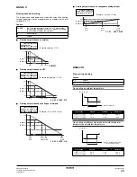
To define the floating setpoint.
To
define the controller display
language.
To set the time and date of the system.
To define the free cooling.
The controller displays the name of the
unit:
MASTER
,
SLAVE1
...
SLAVE3
.
This name is automatically assigned
depending on the set hardware
address. Refer to "Setting the
addresses" in
"Connection and setup of
a DICN system"
in the installation
manual.
To define whether or not a password is
needed to enter the setpoints menu and
for switching the unit on and off.
To define the outlook of the main menu,
to set the logout timer and to define
whether or not the buzzer is to be
activated when errors occur.
To define the backlight time and to
define whether or not graphic readout is
activated.
To enter the service menu (only a
qualified installer is allowed to access
this menu).
_v PUMPCONTROL
PUMPLEADTIME :020s
PUMPLAGTIME :060s
DAILY ON:N AT:12h00
_^ DUAL PUMP
MODE:AUTO ROTATION
OFFSET ON RH :048h
_ FLOATING SETPOINT
MODE:AMBIENT
MAXPOS:03$0¢ NEG:00$0¢
RF:020$0¢ SLOPE:006$0¢
_ LANGUAGE
PRESS ENTER TO
CHANGE LANGUAGE:
ENGLISH
_ TIME AND DATE
TIME: 22h35
DATE FORMAT:DD/MM/YY
DATE: MON 20/03/06
_ FREE COOLING
MODE:AMBIENT
SP: 05$0¢ DIF:01$0¢
PUMP:ON LEAD:000s
_÷ MASTER SETTINGS
MODE:NORMAL
OFFSET:0000h
PUMP ON IF:UNIT ON
_v ADVANCED
PASSWORD NEEDED FOR:
SETPOINT MENU:Y
UNIT ON/OFF:Y
_^ ADVANCED
MAIN MENU:GRAPHIC
LOGOUT TIMER :05min
BUZZER IF SAFETY:YES
_^ ADVANCED
BACKLIGHT TIME:05min
GRAPHIC READOUT:YES
ENTER SERVICE
PASSWORD: 0000
TO LOGIN
To check the actual value of the general
software timer.
To check the actual value of the
compressor timers of circuit 1.
To check the actual value of the
compressor timers of circuit 2 (only for
EWAQ130~260).
To consult information about the unit
safety which caused the shutdown.
To consult information about the
circuit
1 safety which caused the
shutdown.
To consult information about the
circuit
2 safety which caused the
shutdown (only for EWAQ130~260).
To consult information about the
network safety which caused the
shutdown.
To consult information about the unit
warning which caused the shutdown.
To check the time at the moment of the
unit shutdown and to check which was
the evaporator inlet water temperature
setpoint.
To check which were the evaporator
inlet, outlet water and ambient tem-
perature at the moment of shutdown.
To check which was the discharge
temperature of the circuits of circuit 1 at
the moment of shutdown.
To check which was the discharge
temperature of the circuits of circuit 2 at
the moment of shutdown (only for
EWAQ130~260).
To check which was the temperature of
the refrigerant of circuit 1 at the moment
of shutdown.
To check which was the temperature of
the refrigerant of circuit 2 at the moment
of shutdown (only for EWAQ130~260).
To check which were the pressures of
circuit 1 and the status of the fans at the
moment of shutdown.
_v GENERAL TIMERS
LOADUP:000s-DWN:000s
PUMPLEAD :000s
FLOWSTOP :00s
_÷ COMPRESSOR TIMERS
GRD11:000s 12:000s
AREC11:000s 12:000s
M.RT11:000s 12:000s
_^ COMPRESSOR TIMERS
GRD21:000s 22:000s
AREC21:000s 22:000s
M.RT21:000s 22:000s
_v UNIT SAFETY
0F0:EMERGENCY STOP
_v CIRCUIT1 SAFETY
1U1:REV PHASE PROT
_v CIRCUIT2 SAFETY
1U1:REV PHASE PROT
_v NETWORK SAFETY
0U4:PCB COMM.PROBLEM
_v UNIT WARNING
0AE:FLOW HAS STOPPED
_÷ UNIT HISTORY:002
0CA:OUT SENSOR ERR
22h33m00s 23/03/06
COOL INLSP1:012$0¢
_÷ UNIT HISTORY:002
INLET WATER:012$0¢
OUTLET WATER:007$0¢
AMBIENT:006$5¢
_÷ UNIT HISTORY:002
C11 DISCHARGE:010$1¢
C12 DISCHARGE:010$5¢
_÷ UNIT HISTORY:002
C21 DISCHARGE:010$1¢
C22 DISCHARGE:010$5¢
_÷ UNIT HISTORY:002
C1 REFR:000$0¢
_÷ UNIT HISTORY:002
C2 REFR:000$0¢
_÷ UNIT HISTORY:002
HP1:019$0b = 050$0¢
LP1:019$0b = -05$2¢
LOWNOISE:N FAN1:OFF