


EWAP400~540MBYNN
Packaged air-cooled water chillers
4PW22678-1B
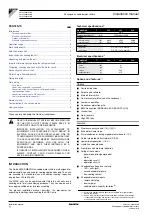
Installation manual
4
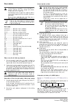
A field supplied blow down port for flushing fluid and
accumulated material from inside the filter can be connected on
the filter end cap.
■
Connecting the counter pipes
Weld the supplied counter pipes to the ends of the water circuit
and connect to the unit with the provided
couplings.
2
Drain taps must be provided at all low points of the system to
permit complete drainage of the circuit during maintenance or in
case of shut down.
3
Air vents must be provided at all high points of the system. The
vents should be located at points which are easily accessible for
servicing.
4
Shut-off valves should be provided at the unit so that normal
servicing can be accomplished without draining the system.
5
Vibration eliminators in all water piping connected to the chiller
are recommended to avoid straining the piping and transmitting
vibration and noise.
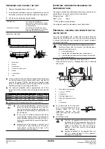
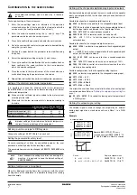
6
For units in a DICN configuration with common leaving water
control, be sure to foresee an insertion hole for the additional
water temperature sensor. Sensor and sensor holder are
optional parts.
The insertion hole shall be 1/4"GAS female thread and should
be located in the mixed waterflow of the chillers.
Make sure that the sensortip is in the waterflow and that you
have a length of straight pipe (L) of at least 5x the pipe diameter
(A) before the sensor.
Choose the position of insertion in a way that the cable length of
the sensor (12 m) is long enough to be attached to the master
PCB.
C
ONNECTING
THE
WATER
CIRCUIT
The evaporator is foreseen of flexible joints for the water inlet and
outlet (refer to the outlook diagram). Evaporator water connections
are to be made in accordance with the outlook diagram, respecting
the water in- and outlet.
If air or dust gets in the water circuit, problems may occur. Therefore,
always take into account the following when connecting the water
circuit:
1.
Use clean pipes only.
2.
Hold the pipe end downwards when removing burrs.
3.
Cover the pipe end when inserting it through a wall so that no dust
and dirt enter.
W
ATER
CHARGE
,
FLOW
AND
QUALITY
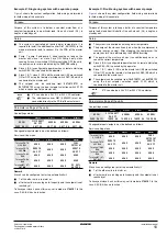
To assure proper operation of the unit, the water flow through the
evaporator must be within the operation range as specified in the
table below and a minimum water volume is required in the system.
The minimum water volume v [l] in the system should fullfill the
criteria below:
The water quality must be in accordance with the specifications listed
in the table below.
P
IPING
INSULATION
The complete water circuit, inclusive all piping, must be insulated to
prevent condensation and reduction of the cooling capacity.
Protect the water piping against water freezing during winter period
(e.g. by using a glycol solution or heatertape).
Minimum water flow
Maximum water flow
EWAP400
565 l/min
2265 l/min
EWAP460
670 l/min
2680 l/min
EWAP540
775 l/min
3100 l/min
Victaulic
®
ØA
L
≥
5 x ØA
>30m
m
>3
0m
m
69m
m
69
m
m
>30m
m
69m
m
v>(Q/2)xt/(Cx
∆
T)
Q
highest cooling capacity of the unit in lowest capacity step within
the range of application (kW)
t
antirecycling timer of unit (AREC)/2(s)=300 s
C
specific heat capacity of the fluidum (kJ/kg°C)=4.186 kJ/kg°C for
water
∆
T
temperature difference between starting and stopping of the
compressor.
∆
T=a+2b+c
(for designation of a, b and c, refer to the operation manual)
NOTE
For units in a DICN configuration, the minimum
required water volume in the system must equal the
biggest required minimum volume of every individual
chiller in the system.
circulating
water
supply
water
tendency if
out of criteria
Items to be controlled
pH
at 25°C
6.8~8.0
6.8~8.0
co
scale
Electrical conductivity
[mS/m]
at 25°C
<40
<30
co
scale
Chloride ion
[mg Cl
–
/l]
<50
<50
corrosion
Sulfate ion
[mg SO
4
2
–
/l]
<50
<50
corrosion
M-alkalinity (pH 4.8)
[mg CaCO
3
/l]
<50
<50
scale
Total hardness
[mg CaCO
3
/l]
<70
<70
scale
Calcium hardness
[mg CaCO
3
/l]
<50
<50
scale
Silica ion
[mg SiO
2
/l]
<30
<30
scale
Items to be referred to
Iron
[mg Fe/l]
<1.0
<0.3
cor
scale
Copper
[mg Cu/l]
<1.0
<0.1
corrosion
Sulfide ion
[mg S
2–
/l]
not
detectable
not
detectable
corrosion
Ammonium ion
[mg NH
4
+
/l]
<1.0
<0.1
corrosion
Remaining chloride
[mg Cl/l]
<0.3
<0.3
corrosion
Free carbide
[mg CO
2
/l]
<4.0
<4.0
corrosion
Stability index
—
—
cor
scale
The water pressure should not exceed the maximum
working pressure of 10 bar.
NOTE
Provide adequate safeguards in the water circuit to
make sure that the water pressure will never exceed
the maximum allowable working pressure.