


Installation manual
3
EWAP400~540MBYNN
Packaged air-cooled water chillers
4PW22678-1B
U
NPACKING
AND
PLACING
THE
UNIT
1
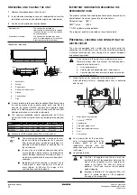
Remove the wooden beams from the unit.
2
Install vibration mountings in case of a roofmounted unit or other
installation where noise and vibration might be an impediment.
3
Set the unit on a solid and level foundation.
Ground level mounting
■
Fix anchor bolts into the concrete foundation. When finally fixing
the unit by means of these anchor bolts, make sure that the
washers for channel DIN434, and both field supplied rubber
plates and field supplied raw cork or rubber sheets for better
vibration protection, are installed as indicated.
■
The concrete foundation should approximately be 100 mm
higher than the floor level for ease of plumbing work and better
drain.
■
Make sure that the foundation surface is even and flat.
I
MPORTANT
INFORMATION
REGARDING
THE
REFRIGERANT
USED
This product contains fluorinated greenhouse gases covered by the
Kyoto Protocol. Do not vent gases into the atmosphere.
Refrigerant type:
R407C
GWP
(1)
value:
1652.5
(1)
GWP = global warming potential
The refrigerant quantity is indicated on the unit name plate.
P
REPARING
,
CHECKING
AND
CONNECTING
THE
WATER
CIRCUIT
The units are equipped with a water inlet and water outlet for
connection to a chilled water circuit. This circuit must be provided by
a licensed technician and must comply with all relevant European
and national regulations.
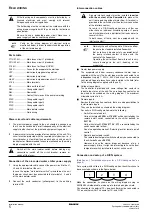
1
Preparing the unit for connection to the water circuit
A box containing
couplings and a filter is delivered
with the unit.
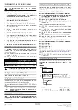
■
As a general rule for this and other
units, it is recommended to check the
insertion depth of the water
temperature sensors into the
connection pipes prior to operation
(see figure).
■
Connecting the filter
Roof mounted:
The unit must be installed on
steelchannel or I-beam frame to support
the unit on the roof, or it can be installed
on a concrete base.
Ground level mounted:
The unit must be installed on a solid
base. It is recommended to fix the unit on
a concrete base with anchor bolts.
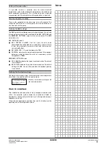
1
Anchor bolt
2
Washer
3
Rubber plate
4
Raw cork or rubber sheet
5
Ground
6
Concrete floor
7
Ditch
Model
A
B
C
D
E
anchor bolt size
Qty
EWAP400
5906
2210
1700
1989
2125
M16x200
8
EWAP460
5906
2210
1700
1989
2125
M16x200
8
EWAP540
5906
2210
1700
1989
2125
M16x200
8
NOTE
■
The measurement tabulated is based on the fact
the base is made in the ground or on a concrete
floor. In case the base is made on a rigid floor, it is
possible to include thickness of concrete floor in
that of the base.
■
In case a base is made on concrete floor, make
sure to provide a ditch as shown. It is important to
extract drainage regardless of whether a base is
made in the ground or on the concrete floor (ditch-
sewerage).
■
Ingredient ratio of the concrete is: cement 1, sand
2 and gravel 3. Insert iron bars of Ø10 mm at
every interval of 300
mm. The edge of the
concrete base should be planed.
>200
>350
100
>100
50
X
X
>B
>A
C
>B
E
D
C
1
2
3+4
5
6
7
X-X
If air or dirt gets in the water circuit, problems may occur.
Therefore, always take into account the following when
connecting the water circuit:
1.
Use clean pipes only.
2.
Hold the pipe end downwards when removing burrs.
3.
Cover the pipe end when inserting it through a wall so that
no dust and dirt enter
1
Water inlet of the evaporator
2
coupling
3
Counter pipe
4
Field water piping circuit
5
Water inlet temperature sensor
6
Filter
7
Filter end cap
■
The filter kit supplied with the unit must be
installed in front of the evaporator water inlet by
means of the supplied
couplings as
shown in the figure. The filter has holes of
diameter 1.0 mm and secures the evaporator
against clogging.
■
Improper installation of the supplied filter will
result in severe damage of the equipment
(freezing of the evaporator).
Victaulic
®
2
3
4
6
5
1
7
2
2
Victaulic
®
≤
50 mm
Victaulic
®