


EWAP400~540MBYNN
Packaged air-cooled water chillers
4PW22678-1B
Installation manual
2
■
Changeable analog input
•
setpoint signal (stand alone unit or slave 1 unit in a DICN system)
0/1 V, 0/10 V, 0/20 mA or 4/20 mA
•
evaporator outlet water sensor of a DICN system (only on master
unit)
■
Multiple language selection
■
Schedule timer
■
Floating setpoint
Standard supplied accessories
■
Filter kit for installation in front of the evaporator water inlet.
O
PERATION
RANGE
M
AIN
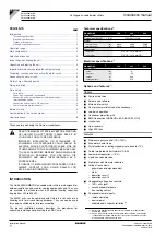
COMPONENTS
(refer to the outlook diagram supplied with
the unit)
1
Evaporator 1
2
Evaporator 2
3
Condenser
4
Compressor 1
5
Compressor 2
6
Discharge stopvalve
7
Liquid stopvalve
8
Suction stopvalve (optional)
9
Chilled water in
10 Chilled water out
11 Leaving water temperature sensor
12 Entering water temperature sensor
13 Drier
14 Power supply intake
15 Emergency stop
16 Switchbox
17 Digital display controller
18 Transportbeam
19 Ambient temperature sensor
20 Field wiring intake
S
ELECTION
OF
LOCATION
This is a class A product. In a domestic environment this product may
cause radio interference in which case the user may be required to
take adequate measures.
The units are designed either for roof mounting or ground level
mounting and should be installed in a location that meets the
following requirements:
1
The foundation is strong enough to support the weight of the unit
and the floor is flat to prevent vibration and noise generation.
2
The space around the unit is adequate for servicing and the
minimum space for air inlet and air outlet (refer to the operation
manual) is available.
3
There is no danger of fire due to leakage of inflammable gas.
4
Select the location of the unit in such a way that neither the
discharged air nor the sound generated by the unit disturb
anyone.
5
Make sure that the air inlet and outlet of the unit are not
positioned towards the main wind direction. Frontal wind will
disturb the operation of the unit. If necessary, use a windscreen
to block the wind.
6
Ensure that water cannot cause any damage to the location in
case it drips out of the unit.
I
NSPECTING
AND
HANDLING
THE
UNIT
At delivery, the unit should be checked and any damage should be
reported immediately to the carrier claims agent.
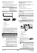
When handling the unit, take into account the following:
1
Lift the unit preferably with a crane and belts in accordance with
the instructions on the unit. The length of the ropes (1) to be
used for lifting are 6 m minimum each.
2
The unit is shipped with wooden beams (2) under it, these have
to be removed before installation.
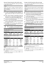
A
Outdoor temperature (°C DB)
B
Leaving water temperature evaporator (°C)
Standard operation range
Standard
Range for pull down operation
Range when adding glycol
B
A
39
43
4
26
-15
0
-5
-10
16
36
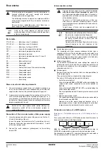
NOTE
Try to reduce the drilling in the unit to a minimum. If
drilling is impreventable, remove the iron filling
thoroughly in order to prevent surface rust!
1
2