Pre-Test Run Checks
ESIE10-01
4–6
Part 4 – Commissioning and Test Run
3
1
4
5
1.4
Water Piping Checks
Checklist
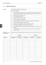
The table below contains the water piping checklist.
Water volume, flow
and pressure
The table below shows the operation range of water volume and water flow for proper operation of the
unit.
Step
Check whether...
1
A filter is installed in front (less than 1 meter) of the water inlet of the heat exchanger. The
heat exchangers are sensitive to dirt and small particles (maximum filter mesh of 1mm).
2
The water volume is within the limits.
3
There is adequate water flow.
4
The water quality meets the standards.
5
The water piping is properly insulated.
6
Measurement points for temperature and pressure are available on the water circuit.
7
The flow switch and pump are properly working.
8
Air purge points are installed on the high parts of the water piping.
9
Drain taps are installed at the low points of the water piping.
10
Other parts of the water circuit are properly mounted and installed (e.g. buffer tank, expan-
sion tank...).
11
Vibration compensators are mounted at the water connections if the unit is positioned on
anti-vibration pads.
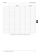
Evaporator
Condenser
Chiller type
Minimum water
volume
Minimum water
flow
Maximum water
flow
Minimum water
flow
Maximum water
flow
Summary of Contents for EWAD620-C17C-SS
Page 2: ......
Page 8: ...ESIE10 01 1 2 Part 1 System Outline 3 1 1 5...
Page 111: ...ESIE10 01 General Outline Part 1 System Outline 1 105 3 1 4 5 1 36 1 Power Compressor 1 2...
Page 112: ...General Outline ESIE10 01 1 106 Part 1 System Outline 3 1 1 4 5 1 36 2 Power Compressor 3...
Page 113: ...ESIE10 01 General Outline Part 1 System Outline 1 107 3 1 4 5 1 36 3 Kit Pumps...
Page 122: ...General Outline ESIE10 01 1 116 Part 1 System Outline 3 1 1 4 5 1 36 12 Digital Inputs Board...
Page 123: ...ESIE10 01 General Outline Part 1 System Outline 1 117 3 1 4 5 1 36 13 Digital Outputs Board...
Page 124: ...General Outline ESIE10 01 1 118 Part 1 System Outline 3 1 1 4 5 1 36 14 Digital Outputs Board...
Page 127: ...ESIE10 01 General Outline Part 1 System Outline 1 121 3 1 4 5 1 36 17 Extension Control Fans 4...
Page 131: ...ESIE10 01 General Outline Part 1 System Outline 1 125 3 1 4 5 1 36 21 EEXV Compressor 1...
Page 134: ...General Outline ESIE10 01 1 128 Part 1 System Outline 3 1 1 4 5 1 36 24 EEXV Compressor 2...
Page 137: ...ESIE10 01 General Outline Part 1 System Outline 1 131 3 1 4 5 1 36 27 EEXV Compressor 3...
Page 138: ...General Outline ESIE10 01 1 132 Part 1 System Outline 3 1 1 4 5 1 36 28 Pumps Control...
Page 139: ...ESIE10 01 General Outline Part 1 System Outline 1 133 3 1 4 5 1 36 29 Terminals M1 M2...
Page 140: ...General Outline ESIE10 01 1 134 Part 1 System Outline 3 1 1 4 5 1 36 30 Terminals M3...
Page 141: ...ESIE10 01 General Outline Part 1 System Outline 1 135 3 1 4 5 1 36 31 Terminals M5 MQ...
Page 148: ...General Outline ESIE10 01 1 142 Part 1 System Outline 3 1 1 4 5...
Page 150: ...ESIE10 01 2 2 Part 2 Functional Description 3 1 2 5...
Page 170: ...The Digital Controller ESIE10 01 2 22 Part 2 Functional Description 3 1 2 4 5...
Page 200: ...Functional Control ESIE10 01 2 52 Part 2 Functional Description 3 1 2 4 5...
Page 202: ...ESIE10 01 3 2 Part 3 Troubleshooting 3 1 3 5...
Page 254: ...Alarms and Events ESIE10 01 3 54 Part 3 Troubleshooting 3 1 3 4 5...
Page 266: ...Controller Inputs and Outputs ESIE10 01 3 66 Part 3 Troubleshooting 3 1 3 4 5...
Page 280: ...ESIE10 01 4 2 Part 4 Commissioning and Test Run 3 1 4 5...
Page 286: ...Pre Test Run Checks ESIE10 01 4 8 Part 4 Commissioning and Test Run 3 1 4 5...
Page 289: ...ESIE10 01 Running Data Part 4 Commissioning and Test Run 4 11 3 4 5 1...
Page 290: ...Running Data ESIE10 01 4 12 Part 4 Commissioning and Test Run 3 1 4 5...


