


ES
IE11-02
Wi
ri
ng
Lay
o
u
t
1–75
3.5
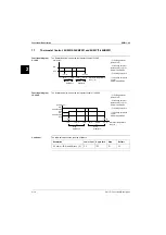
W
iring Diagram: EUWA*5-
24KBZW1 and EUWY*5-24KBZ
W1
Dia
g
ra
m
X3B
F5
RS485 M
odbus
OR
EKRUMCA
connec
tion
A72P
Remot
e
user int
er
fac
e
G
G0
+
-
GND
A71P
GND
-
+
A3P
BL
U
12
11
24
21
12
11
11
14
ONL
Y FOR A
C16-24
FOR HEA
TPUMP ONL
Y
X2
(NO3)
X2
(NO4)
X2
(C3/4)
A1P
FOR HEA
TPUMP ONL
Y
A1P
X2
(C1/2)
X2
(NO2)
X2
(NO1)
BLK
A1P
X3
57(7)
ORG
50(14)
WHT
X55A
X2A
X3A
X4A
X5A
X3M
X11
37 YLW/
GRN
1
2
2
1
OPTION KIT
:
EK
AC10C
OPTION KIT
:
EKRUMCA
( ) APPLICABLE FOR UNIT
WITHOUT INTEGRA
TED PUMP
S7S OPEN = HEA
TING
S7S CL
OSED = C
OOLING
4
3
2
1
ONL
Y FOR
AC16-24 HEA
TPUMP
ONL
Y FOR
AC5-24 HEA
TPUMP
AC16-24
230W
AC16-24
STD: 190W
ESP
: 200W
X2B
AC
5
140W
AC
8-
24
230W
AC
5
STD: 140W
ESP
: 190W
AC
8-
24
STD: 190W
ESP
: 200W
AC16: 8HP
AC20: 10HP
AC24: 12HP
AC
5:
5
HP
AC8 & A
C16: 8HP
AC10 & A
C20: 10HP
AC12 & A
C24: 12HP
ORG
M
1
FOR A
C5
H
C
BLK
RED
M12F
1
FOR A
C8-24
W
V
U
BLK
WHT
RED
H
C
RED
BLK
RED
BLK
ORG
M
H
C
H
C
M
H
C
BLK
RED
ORG
BLK
RED
85 BLK
84 WHT
83 RED
82 BLK
81 WHT
80 RED
W
V
U
W
V
U
43 BLK
45 WHT
44 RED
3 BLK
2 WHT
1 RED
ONL
Y FOR
AC16-24
X1B
5 L3
3 L2
1 L1
5 L3
3 L2
1 L1
6 T3
4 T2
2 T1
6 T3
4 T2
2 T1
5 L3
3 L2
1 L1
5 L3
3 L2
1 L1
6 T3
4 T2
2 T1
6 T3
4 T2
2 T1
6 T3
4 T2
2 T1
5 L3
3 L2
1 L1
ONL
Y FOR A
C16-24
7
8
24V
AC
H6P
X1M (
A2P)
24V
AC
24V
AC
24V
AC
X1M: H3-6P Output t
erminal f
or fieldwiring
(v
oltage fr
ee c
ontac
t max 2A/Output)
X2M: E5H fieldheat
er (max 500W r
esistiv
e / 230V
ac / 50hz)
X3M: S7S,S9S: I
nput t
erminal f
or fieldwiring (don
't c
onnec
t v
oltage)
(swit
ch load 6mA / 30VDC
)
X64A
X42A
ONL
Y FOR
AC16-24 HEA
TPUMP
X41A
ONL
Y FOR
AC5-24 HEA
TPUMP
X40A
A1P
X2
(C3/4)
X2
(NO4)
X2
(NO3)
1
3
5
X51A
71(8)YLW/WHT
73(10) PNK/WHT
72(9)BRN/WHT
DI4
1
3
5
X50A
OTHERS
DIGIT
AL OUTPUT
S (RELA
YS)
DIGIT
AL INPUT
S
ANAL
OG OUTPUT
S
ANAL
OG INPUT
S
compr
essor M1C on
compr
essor M2C on
voltage fr
ee c
ontac
t
for pump
rev
ersing valv
e
alarm v
oltage fr
ee
co
ntac
t
:
:
:
:
:
DIGIT
AL OUTPUT
S (RELA
YS)
flo
w swit
ch
Remot
e C/H selec
tion
high pr
essur
e swit
ch +
dischar
ge pr
ot
ec
tor +
ov
er
curr
ent
lo
w pr
essur
e swit
ch
remot
e On/O
ff
:
:
:
:
:
DIGIT
AL INPUT
S
X1 (B1-
GND
): inlet wat
er t°
X1 (B2-
GND
): outlet wat
er t°
X1 (B3-
GND
): none
X2 (
C1/2-NO1)
X2 (
C1/2-NO2)
X2 (
C3/4-NO3)
X2 (
C3/4-NO4)
X2 (
C5-NO5)
X1 (ID1-
GND
)
X1 (ID2-
GND
)
X1 (ID3-
GND
)
X1 (ID4-
GND
)
X1 (ID5-
GND
)
OPTION: OP10
40 BLK
28 RED
4
FOR UNIT
S WITHOUT INTEGRA
TED PUMP
4
FOR UNIT
S WITH INTEGRA
TED PUMP
X56A
2
/WHT
35GRN
58(6) RED
53(11) BLU
52(12) BLK
51(13) ORG
27 RED/BLK
26 BRN
25 RED/BLK
24 BRN
34 RED
/WHT
69(6) GRY/WHT
54(10) VIO
62(2) PNK
55(9) GRY
63(1) GRN
56(8) BRN
61(3) WHT
31 GRY
30 GRN
28 YLW
29 ORG
17 GRY
16 GRN
22 VIO
23 PNK
15 GRY
14 GRN
20 VIO
21 PNK
33 RED
32 RED
12 RED
13 ORG
12 YLW
11 ORG
10 YLW
8 BL
U
9 BLK
7 RED
19 RED
18 RED
6 BLK
5 WHT
4 RED
3 BLK
2 WHT
1 RED
3
FOR A
C16-24
3
FOR A
C5-12
HAP light emitting diode (ser
vic
e monit
or g
reen)
H1P
,H2P light emitting diode (ser
vic
e monit
or r
ed)
S1A dipswit
ch (unit setting)
S2A dipswit
ch (defr
. & fan setting)
RY1 Rev
ersed phase pr
ot
ec
tor
RY3 P
ump/general oper
ation
RY4-24 F
an speed r
ela
y 1
RY5-25 F
an speed r
ela
y 2
RY
6 Heat
er
tape
RY7 Rev
ersing valv
e cir
c1
RY8 Rev
ersing valv
e cir
c2
RY9 M1C off (during defr
ost)
RY10 M2C off (during defr
ost)
RY12-22 F
an speed r
ela
y 3
RY
27 r
ev
ersing valv
e of wat
er cir
cuit
DI1 Rev
erse phase det
ec
tion (L1-N)
DI2 Rev
erse phase det
ec
tion (N-L3)
DI3 M1C ON det
ec
tion
DI4 M2C ON det
ec
tion
DI5 Saf
et
y devic
e det
ec
tion
DI6 P
ump ON det
ec
tion
DI7 --
DI8 --
DI9 --
DI10 Rev
erse valv
e r
equest
E5H
H3P
H4P
H5P
H6P
Y3R
S9S
S7S
H2P
H1P
HAP
ONL
Y FOR UNIT
S WITH INTEGRA
TED PUMP
X14A
X15A
X12A
X13A
2
FOR A
C5-12
2
ONL
Y FOR
AC16-24
X66A
X65A
X62A
X70A
24V
AC
DI10
X61A
X30A
X78A
X23A
X7
X5
(RPP)
DI2
X60A
X63A
X71A
X71A
X17A
M22F
M21F
X24A
M12F
M11F
X22A
X21A
X1A
X2M
X6
X8
X10A
X8A
X6A
X17A
X11A
X9A
X7A
X19A
X19A
DI1
DI5
X79A
X16A
DI3
X52A
X53A
X18A
ONL
Y FOR 16-24HP
ONL
Y FOR A
C16-24
ONL
Y FOR A
C16-24
ONL
Y FOR A
C16-24
X80A
X10
X9
X3M
FOR A
C16-24
ONL
Y FOR UNIT
S
WITH BUFFER
TANK
X29A
X28A
X27A
DI6
X81A
X82A
1
3
5
7
7
5
3
1
4321
5
6
7
8
9
10
X1M
3
4
5
6
1
2
3
4
5
6
7
8
9
10
38 BLK
39 BLU
2
1
M1P
M1C
M2C
1
3
5
13
13
13
1
2
21
13
31
1
3
111
222
75(12) ORG
36VIO
/WHT
/WHT
42VIO
41GRN
/WHT
86 RED
87 RED
RED
WHT
ST
A1
A2
5 L3
3 L2
1 L1
6 T3
4 T2
2 T1
RED
WHT
BLK
RED
WHT
BLK
RED
WHT
BLK
5
6
RED
GRN
65(2) BLK/WHT
X2
(NO1)
X2
(NO2)
X2
(C1/2)
A1P
70(7)RED/WHT
64(1)BLU/WHT
5
FOR C
OOLING ONL
Y
6
FOR C
OOLING ONL
Y
1/16E
X5
X6
70(7)RED/WHT
64(1)BL
U/WHT
65(2) BLK/WHT
72(9)BRN/WHT
71(8)YLW/WHT
73(10) PNK/WHT
BLU
BLK
YLW
GRY
X7
X8
X4B
X4B
X3B
X3B
PCB: Remot
e user int
er
fac
e
A72P **
auxiliar
y b
ypass r
ela
y
K1A
high pr
essur
e swit
ch during defr
ost cir
cuit 1, cir
cuit 2
S21HP
,S22HP
PCB: P
ow
er supply car
d
A71P **
fuse f
or pumpc
ontac
tor
F6 (#)
fuse I/O PCB
fuse c
ontr
oller PCB
F3U
F1U
PCB: sof
tstar
ter f
or cir
cuit 1
buff
er
tank (55l) heat
er
field heat
er
E6H **
E5H *
H5P *
indication lamp operation c
ompr
essor 2
TR1
transf
o 230V -> 24V f
or supply of c
ontr
oller PCB
Q21F
,Q22F
thermal pr
ot
ec
tor fan cir
cuit 2
compr
essor mot
or cir
cuit 1, cir
cuit 2
M1C,M2C
R7T
,R8T
coil t
emperatur
e sensor f
or cir
cuit 1 ,cir
cuit 2
R6T
ambient t
emper
atur
e sensor
Y1R,Y2R
Rev
erse valv
e cir
cuit 1, cir
cuit 2
A3P **
PCB: addr
ess car
d
PE
main ear
th t
erminal
Q1D
,Q2D
dischar
ge thermal pr
ot
ec
tor cir
cuit 1, cir
cuit 2
Q11F
,Q12F
thermal pr
ot
ec
tor fan cir
cuit 1
R3T
evapor
at
or inlet wat
er t
emperatur
e sensor
R4T
evapor
at
or outlet wat
er t
emper
atur
e sensor
S1HP
,S2HP
high pr
essur
e swit
ch cir
cuit 1, cir
cuit 2
S9S *
swit
ch f
or r
emot
e star
t/st
op or dual setpoint
S10L
flo
w
swit
ch
S12M
main isolat
or swit
ch
S4LP
,S5LP
Lo
w pr
essur
e swit
ch cir
cuit 1, cir
cuit 2
TR2
transf
o 230V -> 24V f
or supply of I/O PCB
X1-82(
A/B/M)
connec
tors
S21P
swit
ch f
or pump: M
anual/A
ut
o
A1P
PCB: c
ontr
oller PCB
E1H,E2H
crankcase heat
er cir
cuit 1, cir
cuit 2
C1,C2,C3,C4
capacit
ors f
or fanmot
ors
E3H,E4H **
evapor
at
or heat
er
tape
F4
fuse I/O PCB & evaporat
or heat
er
tape
F1,F2,F3 #
main fuses f
or the unit
F5 ##
sur
ge pr
oof fuse
H3P *
indication lamp alarm
H4P *
indication lamp operation c
ompr
essor 1
K4
S,
K5
S
ove
rc
ur
re
nt
re
la
y c
irc
ui
t 1
, c
irc
ui
t 2
K1M,K2M
compr
essor c
ontac
tor cir
cuit 1, cir
cuit 2
K1P (*)
pumpc
ontac
tor
M11F
,M12F
fan mot
ors cir
cuit 1
M1P
pump mot
or
X1 (
Y-
GND
):
K6S (*)
ov
er
curr
ent r
ela
y pump
fan mot
ors cir
cuit 2
M21F
,M22F
A2P
PCB: I/O PCB
swit
ch f
or r
emot
e c
ooling/heating selec
tion or dual setpoint
S7S *
indication lamp gener
al oper
ation
H6P *
F7,F8
fuse f
or fan mot
or cir
cuit 1, cir
cuit 2
K21A, K22A
auxiliar
y b
ypass r
ela
y
A5P **
13
24
6
5
8
7
12
11
10
9
13
14
15
16
C
D
E
F
G
H
K
J
L
M
B
A
M
L
J
K
H
G
F
E
D
C
B
A
16
15
14
13
91
0
11
12
78
45
6
23
1
A1
1T
W60006-1
S2A dipswit
ch: Defr
ost & fan setting
1 > only applicable f
or heatpump:
O
ff=star
t c
ondition 1 f
or defr
ost c
ycle
On =star
t c
ondition 2 f
or defr
ost c
ycle (5, 8, 10, 12, 16, 20, 24HP)
2 > O
ff=fansetting 1 (5, 8, 16HP)
On =fansetting 2 (10, 12, 20, 24HP)
S1A dipswit
ch: Unit setting
1 > O
ff=1 cir
cuit
On =2 cir
cuit
234 > O
ff O
ff O
ff =
WC C
O &
WC CL C
O
O
ff On O
ff = A
C C
O
On O
ff O
ff = A
C HP(without c
ompr st
op f
or defr
ost c
ycle)
On O
ff On = A
C HP(with c
ompr st
op f
or defr
ost c
ycle)
51
52
C-16
K22A
K21A
C-15
52
51
11
C-16
C-14
K1A
21
14
24
P>
S22HP
P>
K21A
K1A
S21HP
A1
A2
K1A
EKSS: sof
tstar
t
EKRUMCA = r
emot
e user int
er
fac
e
G0
G
A1P
X1(
G)
X1(
G0)
TR1
230V
0V
0V
24V
TR2
230V
0V
0V
24V
4.4 A
1.9 A
1.9 A
3 A
3 A
Y1R,
Y2R ARE A
CTIV
ATED IN C
OOLING MODE
(11)
F6
M
C2
1
WITHOUT INTEGRA
TED PUMP
6 T3
4 T2
2 T1
5 L3
3 L2
1 L1
2 T1
4 T2
6 T3
5 L3
3 L2
1 L1
(13)
PUMP C
ONT
AC
T FOR UNIT
S
95
96
K6S
A1
A2
K1P
E5H
4.4 A
4.4 A
4.4 A
3 A
1.8 A
1.8 A
1.2 A
14A
17A
24A
--
--
--
24A
17A
14A
24A
17A
14A
315mA
T
315mA
T
315mA
T
315mA
T
315mA
T
315mA
T
5A
5A
5A
5A
5A
5A
250mA
T
250mA
T
250mA
T
250mA
T
250mA
T
250mA
T
8A
8A
8A
8A
8A
8A
3x20A
3x25A
3x25A
3x32A
3x40A
3x50A
3x63A
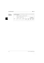
F1,F2,F3 (= gL/gG)
1.9 A
1.2 A
--
9A
315mA
T
5A
250mA
T
8A
3x20A
3x25A
3x32A
3x40A
3x50A
3x50A
3x63A
K6S (
OP PUMP high or +OP
ZH/ZL)
24HP
12HP
16HP
UNIT
S WITHOUT INTEGRA
TED PUMP (400V
)
20HP
FUSES
5HP
8HP
10HP
24HP
12HP
16HP
ALL MODELS (400V
)
20HP
F1U
F5
FUSES +
OVERCURRENT
5HP
8HP
F4
K4S
F3U
10HP
K6S (ST
. PUMP or OP
ZH/ZL)
K5S
DIPSWIT
CH SE
TTING
(12)
TERMINALS FOR FIELDWIRING
(10)
R8T
+t°
R7T
+t°
R6T
+t°
OP PUMP high = H
igh Head pr
essur
e pump
EK
AC10C = addr
ess car
d k
it f
or M
odbus or r
emot
e user int
er
fac
e c
onnec
tion
24HP
12HP
16HP
UNIT
S WITH INTEGRA
TED PUMP (400V
)
20HP
F4
C-1
64
63
63
64
K1P
C-1
C-1
63
51
64
52
K2M
G-2
G-2
G-2
F-12
D-
10
Q21F
Q22F
RY
25
RY
24
RY
22
Q11F
Q12F
RY
5
RY
4
S10L
>
RY
1
H5P
H6P
H3P
RY
27
A1P
A2P
(NO5)
X2
(C
5)
X2
A1P
A1P
R4T
+t°
RY
8
Y2R
RY
7
Y1R
E4H
L
N
R3T
+t°
P<
S4LP
P<
S5LP
S7S
S9S
X1(ID5)
X1(ID4)
X1(ID3)
X1(ID2)
X1(ID1)
X1(
GND
)
X1(
GND
)
X1(B3)
X1(B2)
X1(B1)
A2P
M
C3
1
M
C4
1
F3U
M
3
K6S
K1P
NO
T ST
AND
ARD INCL
UDED
NO
TES :
OBLIGA
TOR
Y
NO
T OBLIGA
TOR
Y
NO
T POSSIBLE AS OPTION
POSS. AS OPTION
*
**
##
#
FUSES
5HP
8HP
F1,F2,F3 (= gL/gG)
EAR
TH WIRING
WIRE 2
TERMINAL 1
FIELD
WIRING
TO BE IN A
CC
ORD
ANCE
WITH
(2)
(1)
L1
S12M
E1H
1
THE L
OCAL ELEC
TRICAL REGULA
TIONS
(8)
IT M
AY BE D
AM
AGED
IF C
OMPRESSOR RO
TA
TES RE
VERSEL
Y,
OP10 = E
vaporat
or heat
er
tape
OPTIONAL
(9)
M
3
K5S
K2M
F1
F2
F3
L1
L2
L3
L2
L3
3N 50H
z 400V
NP
E
N
PE
(3)
(4)
(5)
OPTION
PCB
(6)
Outside swit
chbo
x
(7)
10HP
F1U
M
3
K4S
K1M
M
C1
1
M
C2
1
K1M
51
52
1 L1
3 L2
5 L3
63
51
6 T3
64
52
4 T2
2 T1
K1M
G-1
G-1
G-1
F-12
D-
8
RY
12
RY
6
K4S
96
95
Q1D
S1HP
P>
A2
A1
K1M
RY
9
K5S
96
95
Q2D
S2HP
P>
E2H
K2M
51
52
A2
A1
K2M
RY
10
E3H
A1P
K2M
K1M
H4P
RY
3
E6H
K1P
S21P
K6S
A2
A1
96
95
H6P
5A
5A
5A
5A
5A
5A
5A
F7,F8
F7
F8
A5P
OPTION EKSS
1/7E
A1
A2
A2
A1
K21A
K22A
K1A
K22A
Summary of Contents for EUWY 24KBZW1 Series
Page 2: ......
Page 8: ...ESIE11 02 vi Table of Contents 3 1 4 5...
Page 10: ...Introduction ESIE11 02 viii 3 1 4 5...
Page 12: ...ESIE11 02 1 2 Part 1 System Outline 3 1 1 5...
Page 86: ...Wiring Layout ESIE11 02 1 76 Part 1 System Outline...
Page 88: ...ESIE11 02 2 2 Part 2 Functional Description 3 1 2 5...
Page 128: ...The Digital Controller ESIE11 02 2 42 Part 2 Functional Description 3 1 2 4 5...
Page 130: ...ESIE11 02 3 2 Part 3 Troubleshooting 3 1 3 5...
Page 168: ...ESIE11 02 4 2 Part 4 Commissioning and Test Run 3 1 4 5...
Page 198: ...Test Run and Operation Data ESIE11 02 4 32 Part 4 Commissioning and Test Run 3 1 4 5...
Page 200: ...ESIE11 02 5 2 Part 5 Maintenance 3 1 5...
Page 210: ...ESIE11 02 4 Index 3 1 4 5...