


Installation manual
2
EWWP045~06 ECB2+3MUAW
Packaged water-cooled water chillers
4PW61663-1A - 2012.04
O
PERATION
RANGE
M
AIN
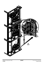
COMPONENTS
(refer to the outlook diagram supplied
with the unit)
1
Compressor
2
Evaporator
3
Condenser
4
Switchbox
5
Chilled water in
6
Chilled water out
7
Condenser water out
8
Condenser water in
9
Evaporator entering water temperature sensor
10
Freeze-up sensor
11
Condenser entering water temperature sensor
12
Digital display controller
13
Power supply intake
S
ELECTION
OF
LOCATION
The units are designed for indoor installation and should be installed
in a location that meets the following requirements:
1
The foundation is strong enough to support the weight of the unit
and the floor is flat to prevent vibration and noise generation.
2
The space around the unit is adequate for servicing.
3
There is no danger of fire due to leakage of inflammable gas.
4
Select the location of the unit in such a way that the sound
generated by the unit does not disturb anyone.
5
Ensure that water cannot cause any damage to the location in
case it drips out of the unit.
The equipment is not intended for use in a potentially explosive
atmosphere.
I
NSPECTING
AND
HANDLING
THE
UNIT
At delivery, the unit should be checked and any damage should be
reported immediately to the carrier claims agent.
U
NPACKING
AND
PLACING
THE
UNIT
1
Cut the straps and remove the cardboard box from the unit.
2
Remove the four screws fixing the unit to the pallet.
3
Level the unit in both directions with the lifting lugs which are
delivered with the control box (ECB*MUAW).
4
Use four anchor bolts with M8 thread to fix the unit in concrete
(directly or using the floor standing supports).
I
MPORTANT
INFORMATION
REGARDING
THE
REFRIGERANT
USED
This product contains fluorinated greenhouse gases covered by the
Kyoto Protocol. Do not vent gases into the atmosphere.
Refrigerant type:
R407C
GWP
(1)
value:
1652.5
(1)
GWP = global warming potential
The refrigerant quantity is indicated on the unit name plate.
C
HECKING
THE
WATER
CIRCUIT
The units are equipped with water inlets and water outlets for connec-
tion to a chilled water circuit and to a hot water circuit. These circuits
must be provided by a licensed technician and must comply with all
relevant European and national regulations.
Before continuing the installation of the unit, check the following
points:
1
A circulation pump must be provided in such a way that it dis-
charges the water directly into the heat exchanger.
2
A flow switch must be installed in the water outlet pipe to prevent
the unit from operating at a water flow which is too low. A
terminal is provided in the switch box for the electrical
connection of the flow switch.
3
A wire mesh strainer (<1 mm) must be installed at the pump
suction as to protect the pump and the heat exchanger from
foreign matter.
4
Drain taps must be provided at all low points of the system to
permit complete drainage of the circuit during maintenance or in
case of shut down.
5
Air vents must be provided at all high points of the system. The
vents should be located at points which are easily accessible for
servicing.
6
Shut-off valves should be provided at the unit so that normal
servicing can be accomplished without draining the system.
7
Vibration eliminators in all water piping connected to the chiller
are recommended to avoid straining the piping and transmitting
vibration and noise.
LWC
Leaving water temperature condenser
LWE
Leaving water temperature evaporator
a
Glycol
b
Water
Continuous operation range
0
10
20
–10
–5
5
32
0
10
20
30
40
50
60
LWC
55
45
ZL
ZL
ZH
ZH
ZL
ZH
-2
-2
–2
a b
a b
a b
The unit is only to be used in a closed water system.
Application in an open water circuit can lead to excessive
corrosion of the water piping.
Summary of Contents for ECB2MUAW
Page 8: ......


