D2CND0 D2CND0 D2TND0
D2TND0 D2TND024A4AA
Wall-mounted condensing boiler
ESIE17-09 / 2017.11
Servicing manual
10
4 Part replacement
3.6
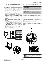
Minimum Installation Clearances
Minimum allowable clearances
a, sides
10 mm
b, Above the casing*
180 mm
c, below
200 mm
f, in front
500 mm
Recommended clearances for easy servicing
d, sides
50 mm
e, below (from the floor)
1500 mm
* 180 mm
is for the case that 60/100 90°C elbow is connect
-
ed to the flue outlet of the boiler
b = 270 mm
in case that 60/100 adapter with measurement
point + 90°C elbow are connected to the flue outlet of the
boiler
b = 270 mm
in case that 60/100 to 80/80 a 90°C
elbow 80 are connected to the flue outlet of the boiler.
b = 320 mm
in case that 60/100 to 80/125 a 90°C
elbow 80/125 are connected to the flue outlet of the boiler.
4.1
Draining the Boiler
4.1.1
Central Heating Circuit
4.1.2
Domestic Hot Water Circuit
•
Isolate the appliance from power supply and closedown
the gas valve.
•
Close all the isolating valves on the central heating
circuit.
•
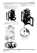
Open the drain valve (1) and drain the central heating
circuit water (a hose can be connected to drain valve).
•
There is another way to drain the central heating water
for the boilers which have internal filling valve. Close the
DHW isolating valve with the central heating isolating
valves. Open a hot water tap and turn the filling valve.
The water inside the boiler will flow from the opened tap.
•
Close the DHW isolating valve and open a hot water
tap. The water inside the plated heat exchanger will flow
from the water tap. Note that a small amount of water
may dwell in heat exchanger.
CH: Central Heating
DHW: Domestic Hot Water
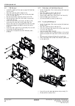
Take out the installation pipes by using wrench
that locate bottom the boiler if you remove flow
hydroblocks or return hydroblocks.
INFORMATION
(1)
Drain the Boiler
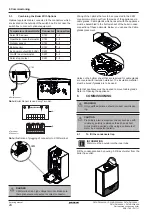
d
b
a
c
f
e
a CH Outlet
b DHW Outlet
c DHW Inlet
d CH Return
e Condensate Syphon Hose Drain Pipe
f Gas Pipe
4
PART REPLACEMENT


