background image

26 

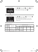
Sub-menu screen

SW  00

–  01

Press   or   button, to move Second Code No., and 
then press   button.

Sub-menu screen

SW  00

–  01

Press   or   button, to scroll to the desired Second 
Code No., and then press   button.

Sub-menu screen

SW  00

–  01

Press   or   button, select “   ”, and then press 

 button to save the setting and return to the previous 

screen. 
If the setting is not changed, select “   ”.

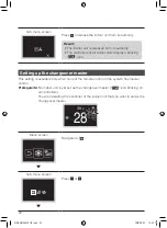
Sub-menu screen

Mode  20
Unit  00

Press   or   button, move to “   ”, and then press 

 button to return to the installer menu.

*  If the setting has been changed, the screen may 

return to the home screen without returning to the 
installer menu.

01_EN_EM19A034_IM.indd   26

2020/09/02   15:53:20

Summary of Contents for BRC1H61W

Page 1: ...onducting the installation of this product and conduct installation according to this manual Refer to this manual together with the installation manual of the indoor unit It is possible to perform set...

Page 2: ...iew of screens 12 Setting screen list 13 Names and Functions 15 Starting up the system 16 Switching the Changeover Master 19 Installer Menu 23 Field Setting 24 R C Setting 31 Installer Password Settin...

Page 3: ...sult in electric shocks or a fire Be sure to use only the specified accessories and parts for installation work Failure to use the specified parts may result in the remote controller falling down elec...

Page 4: ...cause a malfunction of the equipment 4 Where flammable gas may leak where there is carbon fibre or ignitable dust suspensions in the air or where volatile flammables such as thinner or gasoline are h...

Page 5: ...be seen after the remote controller is installed NOTE 3 11 64 80 5 13 64 5 33 64 13 1 47 64 44 9 32 7 R3 32 2 5 R3 32 2 5 13 64 5 41 64 16 25 1 47 64 44 35 64 13 75 3 11 64 80 5 Back plate Through hol...

Page 6: ...piece of the back plate according to the following figure After removing a thin piece with a tool such as clippers remove burrs using a file etc a Wiring from top b Wiring from left c Wiring from bot...

Page 7: ...head wood screws Drywall anchors CAUTION Install the controller on a flat surface only To prevent deformation of the back plate avoid over tightening the installation screws If tightened too much the...

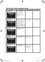
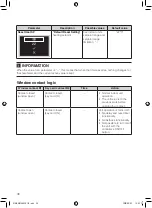
Page 8: ...maintain a 3 8 inch 10 mm difference between the length of the two conductors Cutting guideline L Wiring outlet L Top 5 5 inch 140 mm Left 4 3 inch 110 mm Bottom 3 5 inch 90 mm Rear No requirements C...

Page 9: ...8 Top outlet P1P2 P1P2 terminal Rear outlet P1P2 Left outlet P1P2 01_EN_EM19A034_IM indd 8 2020 09 02 15 53 13...

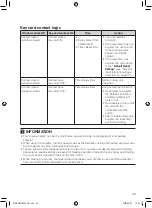
Page 10: ...top of the controller on the top of the back plate 2 Snap the bottom of the controller into place on the bottom of the back plate 3 Ensure the installation site is dust free before peeling the protec...

Page 11: ...roller circuit board is attached to the upper casing Be careful not to damage the circuit board and casing when removing the upper casing Do not touch the remote controller circuit board directly with...

Page 12: ...his button again to turn off the system b Status indicator LED During operation the light ring around the display lights up blue red green Lights up blue Operating Blinks red Error is occurring Lights...

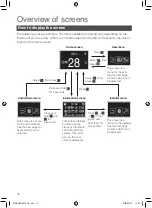
Page 13: ...enu Information screen Installer menu This screen is a menu for the administrator See the next page for items which can be selected 12 34 A3 01 Unit 00 This screen displays the time and the status of...

Page 14: ...rrent setting Vertical Airflow Airflow direction 2 setting Depends on current setting Ventilation Mode Ventilation mode setting Depends on current setting Ventilation Rate Ventilation rate setting Adj...

Page 15: ...t setting Clock Setting Clock setting About Administrator information Admin Password Administrator password setting Installer Password Installer password setting Field Setting Field Setting R C Settin...

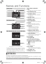
Page 16: ...h Bluetooth Indicates that the controller is communicating with a mobile device for use with the app i Changeover Under Control Displayed when controller is unauthorized to select heating cooling oper...

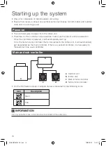
Page 17: ...tically start up If it is the first and only controller that is connected to the indoor unit it will automatically get designated as the main controller If there is a second controller it is necessary...

Page 18: ...RMATION If a sub controller does not display the home screen 2 minutes after its designation turn off the power and check the wiring INFORMATION After re designating a controller the system requires a...

Page 19: ...ode appears press and hold until 2 appears on the screen When the U8 error code appears press and hold until 1 appears on the screen Result A controller displaying 1 is set as main and a controller di...

Page 20: ...s the changeover master Depending on the system this function may not be available Possible operation mode selections for a remote controller that is a changeover master or a mode follower Operation m...

Page 21: ...m When multiple indoor units are connected to the same port of a branch selector unit Give the authority to choose cooling heating or auto to 1 of these remote controllers c c b b c d c b b d d a e f...

Page 22: ...isite You are in the installer menu You are operating the controller of the indoor unit that you want to release from being the changeover master Home screen 30 C 28 Press and hold button for 5 second...

Page 23: ...over master This setting is available only when none of the remote control in the system has master control Prerequisite No indoor unit is yet set as the changeover master icon blinking on all control...

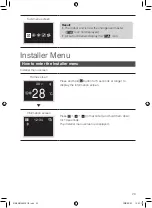
Page 24: ...taller Menu How to enter the Installer menu Installer menu screen Home screen 30 C 28 C Press and hold button for 5 seconds or longer to display the information screen Information screen 12 34 Press i...

Page 25: ...troller side is impossible Disconnect Bluetooth or perform field setting from the mobile application Sub menu screen Mode 20 Unit 00 a b Press or button to select Mode No and press to enter the field...

Page 26: ...Press or button to select and then press button to set the selection Sub menu screen SW 00 01 a b Press or button select First Code No and then press button a First Code No b Second Code No Sub menu...

Page 27: ...00 01 Press or button select and then press button to save the setting and return to the previous screen If the setting is not changed select Sub menu screen Mode 20 Unit 00 Press or button move to an...

Page 28: ...r details about the specific field settings of each type of indoor unit see the installation manual of the indoor unit Field settings that are not available for a connected indoor unit are not display...

Page 29: ...5 000 hrs Long life filter Approx 2 500 hrs Approx 1 250 hrs Standard filter Approx 200 hrs Approx 100 hrs 1 Long life filter type Setting of filter sign indication time Change setting when Ultra lon...

Page 30: ...irection range setting Upper Normal Lower 6 Setting the external static pressure Setting according to the connected duct resistance Normal High static pressure Low static pressure For FHYK Normal High...

Page 31: ...y shipment is set to 01 However for the following cases it is not 01 Airflow direction range setting except Round flow cassette 02 Thermostat sensor in remote controller SPLIT system only 02 Thermosta...

Page 32: ...e is impossible Disconnect Bluetooth or perform field setting from the mobile application Sub menu screen Mode R1 Unit a b Press or button to select Mode No and press to enter the field setting menu a...

Page 33: ...n SW 13 00 Press or button scroll to the desired First code No and then press button to set the selection Sub menu screen SW 13 00 Press or button to move Second Code No and then press button Sub menu...

Page 34: ...the installer menu If the setting has been changed the screen may return to the home screen without returning to the installer menu R C setting mode list Mode No FIRST CODE NO Description SECOND CODE...

Page 35: ...ible Disconnect Bluetooth or perform field setting from the mobile application Sub menu screen 0 0 0 0 a b Press or button select Enable Disable and press to perform password enable disable setting a...

Page 36: ...1 2 3 4 Press or button move to and then press button to return to the installer menu Other Service Settings Group Address Assign the group address and unit number for centralized control The group an...

Page 37: ...not function properly the external input interlock menu is not available in the installer menu In case a centralised controller is additionally part of the system external input interlock is controlle...

Page 38: ...at starts as soon as the Delay Timer expires When this timer expires the previous state i e regular setpoint changes to the Default Reset Setting state 0 20 hours 20 hours Reset ON OFF ON OFF Default...

Page 39: ...rrent active value is kept Window contact logic Window contact B1 Key card contact B2 Time Action Contact closed window open Contact closed key card IN Normal indoor unit operation The unit returns to...

Page 40: ...Setback function is enabled Setback will work or not Not possible to turn on off the unit with the controller s ON OFF button After the delay timer has expired the reset timer will start counting INFO...

Page 41: ...Example 1 1 You remove the key card Result The indoor unit continues operating normally until the delay timer expires 2 You open the window before the delay timer expires Result The indoor unit stops...

Page 42: ...g the window the reset timer will have started counting Closing the window has no influence on the reset timer IF the delay timer HAS NOT expired before closing the window it will expire immediately a...

Page 43: ...ibution THIS SOFTWARE IS PROVIDED BY THE COPYRIGHT HOLDERS AND CONTRIBUTORS AS IS AND ANY EXPRESS OR IMPLIED WARRANTIES INCLUDING BUT NOT LIMITED TO THE IMPLIED WARRANTIES OF MERCHANTABILITY AND FITNE...

Page 44: ...1W SQASI TA 20 1972 For model BRC1H61K SQASI TA 20 1973 In Philippines For model BRC1H61W ESD 2022264C For model BRC1H61K ESD RCE 2022819 In Singapore For model BRC1H61W Complies with IMDA Standards N...

Page 45: ...1H61W Certificate of conformity number 283 CN TT2 For model BRC1H61K Certificate of conformity number 280 CN TT2 DAIKIN Air Conditioning VietNam Joint Stock Company In Australia In New Zealand 01_EN_E...

Page 46: ...EM19A034 2009 HT 00_CV_EM19A034_IM indd 2 2020 09 02 15 54 02...

Reviews: