BRC073A1
Wired user interface
4P392190-1 – 2014.11
Installation and operation manual
8
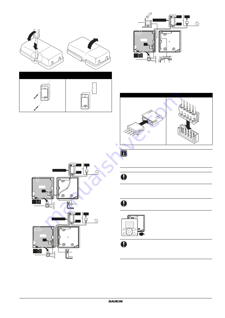
5. Securing the user interface adapter
Remove the upper case of the user interface adapter and secure the
lower case assembly.
6. Wire the indoor unit
For detailed instructions refer to the installation videos available on
http://www.daikineurope.com/support-and-manuals/product-
information/
. More specifically, for how to connect the S21 connector,
refer to the installation videos of the Daikin online controller.
3 methods:
1
from the rear,
2
from the left,
3
from the top,
1
indoor unit
2
notch the part for the wiring to pass through with nippers,
etc.
3
secure the wiring to the upper case using the wiring
retainer and clamp.
Connect the user interface (S1) to the adapter (S19), and the adapter
(S6) to the indoor unit (S21):
7. Attach the upper case
Align the upper case with the tabs of the lower
case (6 points) and insert the upper case (begin
with the bottom part).
Mounting with supplied wood screws
(Ø3.5×16)
Mounting with supplied double-face
adhesive tape
3
1
2
1×
3
1
2
PCB
PCB
S19
S21
S6
S1
1
1×
BRCW901A
2
PCB
1×
2
PCB
3
S19
S21
S6
S1
1
BRCW901A
S1 and S19 connection
S6 and S21 connection
INFORMATION
When wiring, run the wiring away from the power supply
wiring in order to avoid receiving electric noise (external
noise).
NOTICE
Earth both ends of the BRCW901A* option cable.
NOTICE
Be careful not to pinch the wiring when attaching.
NOTICE
1
The switch box and connection wiring are not
included.
2
Do not directly touch the PCB with your hand.
1×
3
3
3
PCB
S19
S21
S6
1
2
S1
PCB
BRCW901A
2
3
4
5
H JST


