Installation and operation manual
3
BRC073A1
Wired user interface
4P392190-1 – 2014.11
2
FAN SPEED
Indicates the fan speed that is set for the air conditioner.
The fan speed will not be displayed if the air conditioner does
not have the fan speed control function.
3
AIRFLOW DIRECTION
Displays the airflow direction that is set for the air conditioner.
The airflow direction will not be displayed if the air conditioner
does not have the airflow direction control function.
Displayed only when the air conditioner is in operation.
4
SET/SETBACK TEMPERATURE DISPLAY
When the unit is turned ON, the temperature that is set for
the air conditioner is displayed.
When the unit is turned OFF and setback is disabled, the
temperature that is set for the air conditioner is displayed.
When the unit is turned OFF and setback is enabled, the
temperature that is set for the setback function is displayed in
smaller digits.
5
ERROR
Indicates a unit error or warning.
Push the button (if enabled) to display the error message
and the maintenance information.
6
TIMER ENABLED
Indicates that the schedule timer or the OFF timer is enabled.
7
UNDER CENTRALISED CONTROL
Indicates that the system is under the management of central
control equipment (optional accessories) and the operation of
the air conditioner through the user interface is prohibited.
8
SETBACK
The setback icon flashes when the unit is turned ON under
setback control.
9
CLOCK (12/24 Hours real time clock)
Indicates that the clock is set.
If the clock is not set, -- : -- will be displayed.
10 DETAILED SELECTION
Is displayed when the detailed display mode is selected.
No detailed items are selected by default.
11 TIMER PROBLEM
Indicates that the clock needs to be set again.
The schedule timer function will not work unless the clock is
set again.
5. Description of the operation modes
1
FAN ONLY OPERATION
In this mode, the air is circulated without being heated or cooled.
2
DRY OPERATION
In this mode, the air humidity will be lowered by intermittently
turning the air conditioner ON in cooling and OFF again to
minimise the temperature decrease.
The temperature and fan speed are controlled automatically
and cannot be controlled by the user interface.
Dry operation will not function if the room temperature is too
low.
3
AUTOMATIC OPERATION
In this mode, the user interface will automatically switch
between heating and cooling as required by the setpoint.
4
COOLING OPERATION
In this mode, cooling will be activated as required by the setpoint
or setback operation.
5
HEATING OPERATION
In this mode, heating will be activated as required by the
setpoint or setback operation.
6
SETBACK
The setback function will maintain the room temperature in a
specific range when the user interface is turned OFF. This is
done by temporarily starting the air conditioner that was
previously turned OFF by the user, the schedule function or the
OFF timer.
For example:
If the room temperature drops below 10°C, heating is started
automatically. If after half an hour the temperature increases
to 12°C or above, the user interface returns to its original
state.
If the room temperature goes above 35°C, cooling is started
automatically. If after half an hour the temperature decreases
to 33°C or below, the user interface returns to its original
state.
The differential can be adjusted in the setback menu. The
setback temperature can be set while the unit is turned OFF on
the basic screen, or can be set in the schedule.
The status of setback (enabled/disabled) can be seen in the
Energy Saving List.
By default, the setback function is disabled. Before enabling
it, first consult the detailed information about
SETBACK
in the
user reference guide.
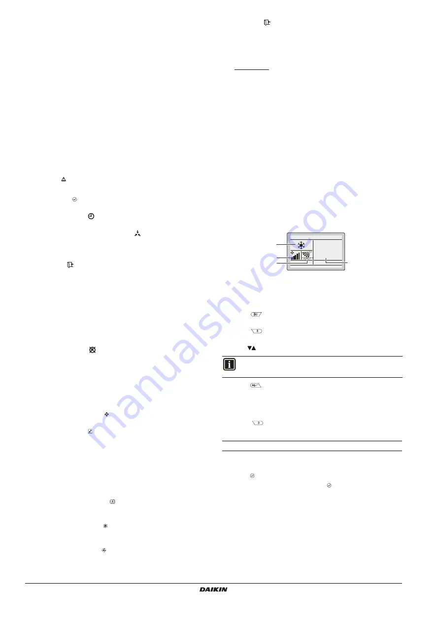
6. Basic operation method
A
Operation mode
B
Temperature:
Indicates the temperature set for the air conditioner.
C
Fan speed.
D
Airflow direction
1
Push
several times until the desired operation mode
Cool
,
Heat
,
Fan
,
Dry
or
Auto
is selected.
2
Push
. The operation lamp (green) will be lit and the air
conditioner will start operating.
3
Use
to set the temperature.
4
Push
to select:
the desired fan speed from
Auto
,
low
,
medium-low
,
medium
,
medium-high
or
high
(depending on the model).
the desired
air flow direction
,
swing
or
no swing
.
5
Push
. The operation lamp will turn OFF and the air
conditioner will stop operating.
Additional features of the controller: KEY LOCK
1
Disable the Menu/Enter and Cancel button. To disable, refer to
"10. Enable/disable the menu/enter and cancel button" on page 9
.
2
Push for 4 seconds to enable the key lock mode.
3
To cancel the key lock mode, push for 4 seconds.
INFORMATION
When in
Dry
mode, the fan speed cannot be set.
28
°C
A
C
B
D


