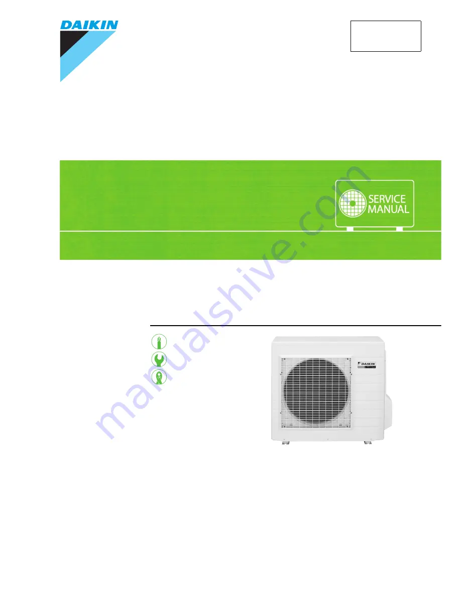
REMOVAL
PROCEDURE
S E R V I C E M A N U A L
Outdoor Unit
Inverter / Hybrid
Pair Type
4.2/5.0/6.0/7.1 kW Class
Si00-875
Page 1: ...REMOVAL PROCEDURE S E R V I C E M A N U A L Outdoor Unit Inverter Hybrid Pair Type 4 2 5 0 6 0 7 1 kW Class Si00 875 ...
Page 2: ...LT ARXS50E3V1B RXS42GVLT RKS60FBVMA ARXS50G2V1B RKS50G2V1B RXS50G2V1B RKS50FVM RXS50FBV2C RKS60FVM RKS50GVMG RYN50FV1A RKS71FVM RKS60GVMG RXS50FBVMA RYN60FV1A RKS71GVMG RXS60FBVMA RKS50FVLT RKS60FVLT RXS71FMV2C RKS71FVLT RXS50FVLT RKS50FVMA RXS60FVLT RKS60FVMA RXS71FVLT RXS50FVMA RXS60FVMA ...
Page 3: ...al of Electrical Box 8 4 Removal of PCBs 12 5 Removal of Sound Blankets Thermistors 15 6 Removal of Four Way Valve 17 7 Removal of Electronic Expansion Valve 18 8 Removal of Compressor 19 Note The illustrations may be slightly different depending on the model The illustrations are for heat pump models as representative ...
Page 4: ...before disassembling work Step Procedure Points 1 Remove the panels Take care not to cut your finger by the fins of the outdoor heat exchanger 1 Remove the 4 screws and lift the top panel 2 Remove the 4 screws and remove the discharge grille Slide the discharge grille upward and remove it The discharge grille has 4 hooks Top panel R12283 R12315 Discharge grille R5245 R5246 ...
Page 5: ...o unfasten the hooks 5 Unfasten the left side hooks and then the right side hook Remove the front panel Lift the front panel while pushing the left side panel inward Lift the front panel and unfasten the right side hook Step Procedure Points Front panel R12284 Shield plate R13626 1 Push the front panel 2 Lift the shield plate upward R5249 R5250 ...
Page 6: ...e right side of the front panel first 2 Remove the stop valve cover 1 Remove the screw of the stop valve cover 2 Pull the stop valve cover downward to unfasten the hooks and remove it The stop valve cover has 6 hooks Step Procedure Points R5251 Stop valve cover R5252 R5253 R5254 ...
Page 7: ...rocedure Points 1 Remove the electrical box cover Preparation Remove the top panel and the front panel according to the Removal of Outer Panels This procedure is not necessary to remove the outdoor fan only 1 Remove the screw of the shield plate 2 Unfasten the 2 hooks and remove the shield plate 3 Unfasten the 4 hooks of the electrical box cover and remove it R5255 Shield plate Hook R12029 Electri...
Page 8: ...r for the fan motor S70 2 Release the fan motor lead wire from the 7 hooks 3 Remove the nut of the outdoor fan Nut size M6 When reassembling align the mark of the outdoor fan with the D cut section of the motor shaft Step Procedure Points S70 R5259 Fan motor lead wire R5260 R5262 Outdoor fan 10 mm R12236 R5263 ...
Page 9: ...n motor may tilt down or fall and cause injury because its center of gravity is shifted to the front 5 Then remove the 2 upper screws 6 Release the fan motor lead wire from the 2 hooks and pull the fan motor out When reassembling put the fan motor lead wire through the back of the fan motor so as not to be entangled with the outdoor fan Step Procedure Points R5264 Fan motor R5265 Fan motor lead wi...
Page 10: ...late Preparation Remove the top panel and the front panel according to the Removal of Outer Panels 2 Slide the shield plate upward to unfasten the hook on the bottom left and then remove the shield plate 3 Remove all the screws of the terminal boards and of the earth wires Disconnect the power supply wire and the connection wire 4 Disconnect the 2 earth wires R17060 Shield plate R17021 Hook R17239...
Page 11: ...ews of the right side panel 6 Remove the screw of the electrical box 7 Unfasten the hooks and remove the right side panel When reassembling insert the upper hook and the 2 lower hooks back into place Step Procedure Points R17241 Right side panel R17242 R5272 Hook R13586 Hook ...
Page 12: ...he relay connector for the compressor 10 Release the clamp 11 Release the clamp by pliers Some models do not have the clamp 12 Detach the clamp and release the thermistor lead wires from the hook Step Procedure Points R17137 S40 S20 S90 S80 Thermistor ASSY harness Electronic expansion valve coil harness Fan motor lead wire R17138 R17139 R5277 R17140 Thermistor lead wire Hook Fixing position for th...
Page 13: ...ectrical Box Removal Procedure 11 13 Remove the screw 14 Release the harness of the outdoor temperature thermistor from the hook 15 Lift and remove the electrical box Step Procedure Points R12316 R9403 R13587 Electrical box ...
Page 14: ...rk Step Procedure Points 1 Disconnect the connectors S52 S102 from the service monitor PCB Preparation Remove the electrical box according to the Removal of Electrical Box 2 Detach the 4 clamps with pliers and remove the service monitor PCB 3 Remove the screws of the terminal board and the earth wire R16707 Service monitor PCB S52 S102 Clamp R16708 R17030 Terminal board Earth wire ...
Page 15: ...ctor for standby electricity saving from the terminal board 1 Black 2 White 3 Red L1 Black L2 Brown N1 White N2 Blue Some models have no relay connector for standby electricity saving 7 Disconnect the 2 connectors for the reactor HR1 HR2 Step Procedure Points R5283 R5284 R13542 N2 N1 L1 3 2 1 L2 Relay connector for standby electricity saving R11473 HR2 HR1 ...
Page 16: ...emoval of PCBs Si00 875 14 Removal Procedure 8 Remove the 3 screws of the main PCB 9 Unfasten the 4 hooks 10 Lift up and remove the main PCB Step Procedure Points Main PCB R5287 R5288 Hook Main PCB R5289 ...
Page 17: ...utes or more after turning off all power supplies before disassembling work Step Procedure Points 1 Remove the sound blanket top upper The design of the sound blankets varies depending on the model 2 Remove the sound blanket top lower 3 Remove the sound blanket back R16962 Sound blanket top upper Sound blanket top lower R16783 Sound blanket back R11161 ...
Page 18: ...carefully 5 Remove the sound blanket inner 6 Release the discharge pipe thermistor Be careful not to lose the clip for the thermistor 7 Cut the clamp and pull out the outdoor heat exchanger thermistor Step Procedure Points R17062 Sound blanket outer Sound blanket inner R16778 R17061 Discharge pipe thermistor R12287 Clip Outdoor heat exchanger thermistor R5292 Clamp ...
Page 19: ...rant gas Cautions for restoration 1 Restore the piping by non oxidation brazing 2 It is required to prevent the carbonization of the oil inside the four way valve and the deterioration of the gaskets affected by heat Keep below 120 C For the sake of this wrap the four way valve with wet cloth and provide water so that the cloth does not dry Note Never use a metal saw to cut pipes because the sawdu...
Page 20: ... the gas brazing machine Warning If the refrigerant gas leaks during work ventilate the room If the refrigerant gas is exposed to flames toxic gas may be generated Caution From the viewpoint of global environment protection do not discharge the refrigerant gas in the atmosphere Make sure to collect all the refrigerant gas Before working make sure that the refrigerant gas is empty in the circuit Be...
Page 21: ...or Procedure Warning Be sure to wait for 10 minutes or more after turning off all power supplies before disassembling work Step Procedure Points 1 Remove the terminal cover 2 Disconnect the lead wires of the compressor R5301 Terminal cover R5302 Red U Yellow V Blue W R12436 ...
Page 22: ...ed Warning Since it may happen that the refrigerant oil in the compressor catches fire prepare wet cloth so as to extinguish fire immediately Caution From the viewpoint of global environment protection do not discharge the refrigerant gas in the atmosphere Make sure to collect all the refrigerant gas Before working make sure that the refrigerant gas is empty in the circuit Be sure to apply nitroge...
Page 23: ...dry In case of difficulty with gas brazing machine 1 Disconnect the brazed part where is easy to disconnect and restore 2 Cut pipes on the main unit with a tube cutter in order to make it easy to disconnect Note Never use a metal saw to cut pipes because the sawdust may enter the circuit When withdrawing the pipes be careful not to pinch them firmly with pliers The pipes may get deformed Provide a...
Page 24: ...Revision History Month Year Version Revised contents 06 2013 Si00 875 First edition ...
Page 25: ...sories supplied or specified by Daikin Ask a qualified installer or contractor to install those parts and accessories Use of unauthorised parts and accessories or improper installation of parts and accessories can result in water or refrigerant leakage electrical shock fire or explosion z Read the User s Manual carefully before using this product The User s Manual provides important safety instruc...