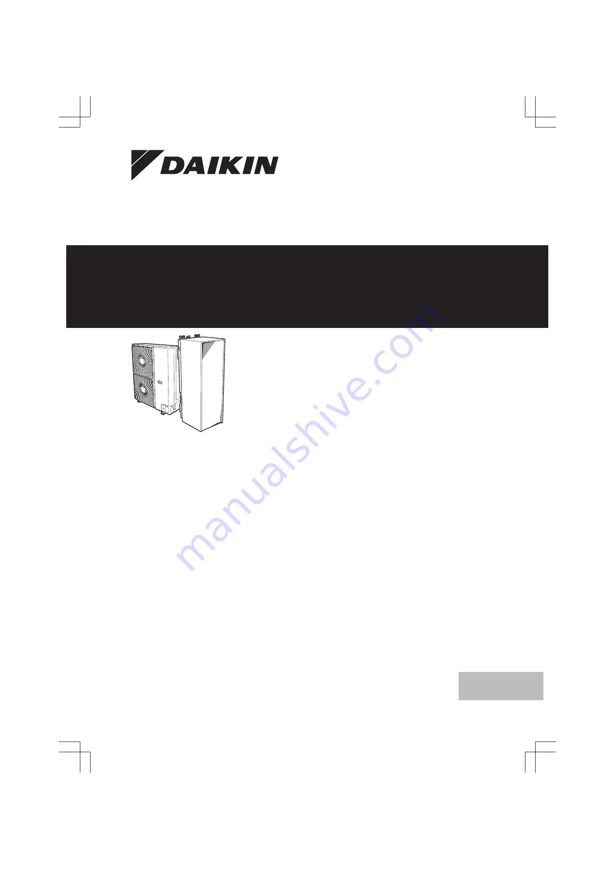
Installer reference guide
Daikin Altherma – Low temperature split
English
+
ERHQ011-014-016BAERLQ011-014-016CA
EHVH/X11+16S18CBEHVH/X11+16S26CB
Page 1: ...staller reference guide Daikin Altherma Low temperature split English Installer reference guide Daikin Altherma Low temperature split ERHQ011 014 016BA ERLQ011 014 016CA EHVH X11 16S18CB EHVH X11 16S26CB ...
Page 2: ...paring water piping 24 6 4 1 Water circuit requirements 24 6 4 2 Formula to calculate the expansion vessel pre pressure 25 6 4 3 To check the water volume and flow rate 25 6 4 4 Changing the pre pressure of the expansion vessel 26 6 4 5 To check the water volume Examples 26 6 5 Preparing electrical wiring 26 6 5 1 About preparing electrical wiring 26 6 5 2 About preferential kWh rate power supply ...
Page 3: ... 9 Commissioning 75 9 1 Overview Commissioning 75 9 2 Precautions when commissioning 75 9 3 Checklist before commissioning 75 9 4 Checklist during commissioning 75 9 4 1 To check the minimum flow rate 76 9 4 2 Air purge function 76 9 4 3 To perform a test run 77 9 4 4 To perform an actuator test run 77 9 4 5 Underfloor heating screed dryout 77 10 Hand over to the user 79 11 Maintenance and service...
Page 4: ...o prevent that the unit can be used as a shelter by small animals Small animals that make contact with electrical parts can cause malfunctions smoke or fire CAUTION Do NOT touch the air inlet or aluminium fins of the unit NOTICE Do NOT place any objects or equipment on top of the unit Do NOT sit climb or stand on the unit NOTICE Works executed on the outdoor unit are best done under dry weather co...
Page 5: ... refer to the nameplate of the unit It states the type of refrigerant and necessary amount The unit is factory charged with refrigerant and depending on pipe sizes and pipe lengths some systems require additional charging of refrigerant Only use tools exclusively for the refrigerant type used in the system this to ensure pressure resistance and prevent foreign materials from entering into the syst...
Page 6: ... compatible with the inverter resistant to high frequency electric noise to avoid unnecessary opening of the earth leakage protector NOTICE Precautions when laying power wiring Do NOT connect wiring of different thicknesses to the power terminal block slack in the power wiring may cause abnormal heat When connecting wiring which is the same thickness do as shown in the figure above For wiring use ...
Page 7: ... system Preparation What to do and know before going on site Installation What to do and know to install the system Configuration What to do and know to configure the system after it is installed Commissioning What to do and know to commission the system after it is configured Hand over to the user What to give and explain to the user Maintenance and service How to maintain and service the units T...
Page 8: ...t 4 Push on the button on the bottom of the front plate 5 Remove the front plate WARNING Sharp edges Take the front plate on the upper part instead of the lower part Watch your fingers there are sharp edges on the lower part of the front plate a e h g f 5 4 1 2 3 4 4 2 6 Remove the accessories 1 1 1 1 1 2 1 2 a b c d f g e h a General safety precautions b Addendum book for optional equipment c Ind...
Page 9: ...nction of the demand PCB is applicable For installation instructions see the installation manual of the demand PCB Snow cover EK016SNC only for ERLQ Prevents the outdoor unit from being snowed up Recommended in areas with low ambient temperatures or heavy snowfall For installation instructions see the installation manual of the snow cover Drain plug kit EKDK04 only for ERHQ Gathers the condensate ...
Page 10: ...ctions see the installation manual of the demand PCB and addendum book for optional equipment Remote indoor sensor KRCS01 1 By default the internal user interface sensor will be used as room temperature sensor As an option the remote indoor sensor can be installed to measure the room temperature on another location For installation instructions see the installation manual of the remote indoor sens...
Page 11: ...e room frost protection is only possible if the leaving water temperature control on the unit s user interface is turned ON INFORMATION In case an external room thermostat is used and room frost protection needs to be guaranteed in all conditions then you have to set auto emergency A 6 C to 1 5 2 1 Single room Under floor heating or radiators Wired room thermostat Setup B A a A Main leaving water ...
Page 12: ...ler of the heat pump convectors The heat pump convectors are directly connected to the indoor unit The desired room temperature is set via the remote controller of the heat pump convectors The space heating cooling demand signal is sent to one digital input on the indoor unit X2M 1 and X2M 4 The space operation mode is sent to the heat pump convectors by one digital output on the indoor unit X2M 3...
Page 13: ...at emitters is the same you do NOT need a mixing valve station cost effective Example If the heat pump system is used to heat up one floor where all the rooms have the same heat emitters Under floor heating or radiators Thermostatic valves If you are heating up rooms with under floor heating or radiators a very common way is to control the temperature of the main room by using a thermostat this ca...
Page 14: ...M 4 The indoor unit will only supply leaving water temperature when there is an actual demand INFORMATION To increase comfort and performance Daikin recommends to install the valve kit option EKVKHPC on each heat pump convector Configuration Setting Value Unit temperature control A 2 1 7 Code C 07 1 Ext RT control Unit operation is decided by the external thermostat Number of water temperature zon...
Page 15: ...one in relation to the required capacity of both water temperature zones For the main zone A mixing valve station is installed before the under floor heating The pump of the mixing valve station is controlled by the ON OFF signal on the indoor unit X2M 5 and X2M 7 normal closed shut off valve output The room temperature is controlled by the user interface which is used as room thermostat For the a...
Page 16: ...Shut off valve g Motorised 3 way valve h Non return valve field supply i Shut off valve field supply j Collector field supply k Auxiliary boiler field supply l Aquastat valve field supply m DHW tank EHBH X option n Heat exchanger coil FHL1 3 Under floor heating NOTICE Make sure the auxiliary boiler and its integration in the system complies with applicable legislation Daikin is NOT responsible for...
Page 17: ... can set the DHW tank temperature at a higher temperature example 53 C which is then mixed with cold water example 15 C Selecting the volume and desired temperature for the DHW tank consists of 1 Determining the DHW consumption equivalent hot water volume at 40 C 2 Determining the volume and desired temperature for the DHW tank Determining the DHW consumption Answer the following questions and cal...
Page 18: ...UT i Recirculation connection By connecting a DHW pump instant hot water can be available at the tap The DHW pump and the installation are field supply and the responsibility of the installer For more information about connecting the recirculation connection for integrated DHW tank see 7 Installation on page 28 for separate DHW tank see installation manual of DHW tank Configuration For more inform...
Page 19: ...te power supply General rule One power meter that covers the entire system is sufficient Setup Connect the power meter to X5M 7 and X5M 8 Power meter type In case of Use a power meter Single phase outdoor unit Backup heater supplied from a single phase grid i e the backup heater model is 3V or 9W connected to a single phase grid Single phase In case of Use a power meter In other cases i e a three ...
Page 20: ...itation is useful to assure a maximum power or current input of the system In some countries legislation limits the maximum power consumption for space heating and DHW production Pi t DI a b Pi Power input t Time DI Digital input power limitation level a Power limitation active b Actual power input Setup and configuration No additional equipment needed Set the power consumption control settings in...
Page 21: ...Ph Ce a b c d e A B C Ph Produced heat Ce Consumed energy A Outdoor unit B Booster heater C Backup heater a Limited outdoor unit operation b Full outdoor unit operation c Booster heater turned ON d Backup heater step 1 turned ON e Backup heater step 2 turned ON 5 7 Setting up an external temperature sensor You can connect one external temperature sensor It can measure the indoor or outdoor ambient...
Page 22: ...peration noise will cause no trouble Note If the sound is measured under actual installation conditions the measured value might be higher than the sound pressure level mentioned in Sound spectrum in the data book due to environmental noise and sound reflections In places where a mineral oil mist spray or vapour may be present in the atmosphere Plastic parts may deteriorate and fall off or cause w...
Page 23: ...0 10 10 mm The foundation must be strong enough to bear the weight of the unit Take the weight of the unit with a domestic hot water tank full of water into account Make sure in the event of a water leak water cannot cause any damage to the installation space and surroundings Do NOT install the unit in places such as In places where a mineral oil mist spray or vapour may be present in the atmosphe...
Page 24: ...n the flow is lower the indoor unit will stop operation and display error 7H Minimum required flow rate during defrost backup heater operation 04 08 models 12 l min 11 16 models 15 l min Field supply components Water Only use materials that are compatible with water used in the system and with the materials used in the indoor unit Field supply components Water pressure and temperature Check that a...
Page 25: ...he recirculation connection of the domestic hot water tank c d a b a Recirculation connection b Hot water connection c Shower d Recirculation pump 6 4 2 Formula to calculate the expansion vessel pre pressure The pre pressure Pg of the vessel depends on the installation height difference H Pg 0 3 H 10 bar 6 4 3 To check the water volume and flow rate The indoor unit has an expansion vessel of 10 li...
Page 26: ...missioning on page 75 6 4 4 Changing the pre pressure of the expansion vessel NOTICE Only a licensed installer may adjust the pre pressure of the expansion vessel When changing the default pre pressure of the expansion vessel 1 bar is required take following guidelines into account Only use dry nitrogen to set the expansion vessel pre pressure Inappropriate setting of the expansion vessel pre pres...
Page 27: ...ite where this equipment is to be installed to know whether it is appropriate to connect the equipment in one of the preferential kWh rate power supply delivery systems available if any When the equipment is connected to such preferential kWh rate power supply the electricity company is allowed to interrupt power supply to the equipment for certain periods of time demand that the equipment only co...
Page 28: ...ons are indicated on the inside of the indoor unit Backup heater type Power supply Required number of conductors 3V 1 230 V 2 GND 9W 1 230 V 2 GND 2 bridges 3 230 V 3 GND 1 bridge 3 400 V 4 GND 7 Installation 7 1 Overview Installation This chapter describes what you have to do and know on site to install the system Typical workflow Installation typically consists of the following stages 1 Mounting...
Page 29: ...he unit from falling over 5 Protecting the unit against snow and wind by installing a snow cover and baffle plates See Preparing installation site in 6 Preparation on page 22 7 3 2 Precautions when mounting the outdoor unit INFORMATION Also read the precautions and requirements in the following chapters General safety precautions Preparation 7 3 3 To provide the installation structure Check the st...
Page 30: ...under the outdoor unit 150 mm Drain holes Model Bottom view mm ERHQ_V3 58 16 16 71 117 102 70 45 376 191 a b c d 4 Model Bottom view mm ERHQ_W1 45 43 378 10 60 58 16 71 16 191 117 102 a b c d 4 ERLQ 35 36 61 99 16 71 60 159 154 182 a b c d 4 a Discharge side b Drain holes c Knockout hole piping intake downwards route d Anchor points 7 3 6 To prevent the outdoor unit from falling over In case the u...
Page 31: ...recautions Preparation DANGER RISK OF BURNING CAUTION Do NOT use mineral oil on flared part Do NOT reuse piping from previous installations NEVER install a drier to this R410A unit to guarantee its lifetime The drying material may dissolve and damage the system NOTICE Take the following precautions on refrigerant piping into account Avoid anything but the designated refrigerant to get mixed into t...
Page 32: ...tch type Conventional flare tool Clutch type Ridgid type Wing nut type Imperial type A 0 0 5 mm 1 0 1 5 mm 1 5 2 0 mm 5 Check that the flaring is properly made a b c a Flare s inner surface MUST be flawless b The pipe end MUST be evenly flared in a perfect circle c Make sure the flare nut is fitted 7 5 6 To braze the pipe end The indoor unit and outdoor unit have flare connections Connect both end...
Page 33: ...r handling the stop valve tighten the stem cap and check for refrigerant leaks Item Tightening torque N m Stem cap liquid side 13 5 16 5 Stem cap gas side 22 5 27 5 To handle the service cap ALWAYS use a charge hose equipped with a valve depressor pin since the service port is a Schrader type valve After handling the service port tighten the service port cap and check for refrigerant leaks Item Ti...
Page 34: ...rying Running the system with the stop valves closed may break the compressor 7 5 9 To connect the refrigerant piping to the indoor unit 1 Connect the liquid stop valve from the outdoor unit to the refrigerant liquid connection of the indoor unit b a a Refrigerant liquid connection b Refrigerant gas connection 2 Connect the gas stop valve from the outdoor unit to the refrigerant gas connection of ...
Page 35: ...alt which absorbs moisture that will freeze when the piping gets cold and or lead to corrosion of flared joints soap water may contain ammonia which causes a corrosive effect between the brass flare nut and the copper flare 1 Charge the system with nitrogen gas up to a gauge pressure of at least 200 kPa 2 bar It is recommended to pressurize to 3000 kPa 30 bar in order to detect small leaks 2 Check...
Page 36: ... Also read the precautions and requirements in the following chapters General safety precautions Preparation 7 7 3 To determine the additional refrigerant amount If the total liquid piping length is Then 10 m Do NOT add additional refrigerant If the total liquid piping length is Then 10 m R total length m of liquid piping 10 m 0 054 R Additional charge kg rounded in units of 0 1 kg INFORMATION Pip...
Page 37: ... water out b Space heating cooling water in c Domestic hot water out d Domestic cold water in cold water supply NOTICE It is recommended to install shut off valves to domestic cold water in and domestic hot water out connections These shut off valves are field supplied NOTICE To avoid damage to the surroundings in case of water leakage it is recommended to close the domestic cold water inlet shut ...
Page 38: ... is recommended to use a tundish 7 8 6 To fill the water circuit 1 Connect the water supply hose to the fill valve 2 Open the fill valve 3 Make sure that the automatic air purge valve is open at least 2 turns 4 Fill the circuit with water until the manometer indicates a pressure of 2 0 bar 5 Purge as much air as possible from the water circuit 6 Close the fill valve 7 Disconnect the water supply h...
Page 39: ...ltage changes voltage fluctuations and flicker in public low voltage supply systems for equipment with rated current 75 A It is the responsibility of the installer or user of the equipment to ensure by consultation with the distribution network operator if necessary that the equipment is connected only to a supply with a system impedance Zsys less than or equal to Zmax EN IEC 61000 3 12 provided t...
Page 40: ...re maximum values see electrical data of combination with indoor units for exact values 7 9 6 To connect the electrical wiring on the outdoor unit NOTICE Follow the wiring diagram delivered with the unit located at the inside of the service cover Make sure the electrical wiring does NOT obstruct proper reattachment of the service cover 1 Remove the service cover See 7 2 2 To open the outdoor unit ...
Page 41: ... to prevent the edge of the knockout hole from cutting the wires a b c d e A B A Inside of the outdoor unit B Outside of the outdoor unit a Wire b Bush c Nut d Frame e Hose 6 Reattach the service cover See 7 10 2 To close the outdoor unit on page 47 7 Connect an earth leakage circuit breaker and fuse to the power supply line 7 9 7 To reposition the air thermistor on the outdoor unit This task is o...
Page 42: ...Changeover to external heat source control Space cool heat operation control CAUTION Do NOT push or place redundant cable length in the unit 7 9 9 To connect the main power supply 1 Connect the main power supply In case of normal kWh rate power supply X1M 1 2 3 1 2 3 X2M X5M X6YB X6YA X6Y X1A X19A 3031 a Legend see illustration below In case of preferential kWh rate power supply Connect X6Y to X6Y...
Page 43: ...system It is the responsibility of the installer or user of the equipment to ensure by consultation with the distribution network operator if necessary that the equipment is connected only to a supply with a system impedance Zsys less than or equal to Zmax 1 Connect the backup heater power supply For 3V models a double pole fuse is used for F1B For 9W models a 4 pole fuse is used for F1B 2 If requ...
Page 44: ...indoor unit for control close to the indoor unit 1 user interface in the room used as room thermostat The procedure differs slightly depending on where you install the user interface At the indoor unit In the room 1 Connect the user interface cable to the indoor unit Fix the cable with cable ties to the cable tie mountings X2M X5M A2P A2P 2 1 a b a Main user interface a b Optional user interface 2...
Page 45: ...ter with transistor output check the polarity The positive polarity MUST be connected to X5M 7 and X5M 9 the negative polarity to X5M 8 and X5M 10 1 Connect the electrical meters cable to the appropriate terminals as shown in the illustration below X2M X5M 78910 S2S S3S 2 Fix the cable with cable ties to the cable tie mountings 7 9 14 To connect the domestic hot water pump 1 Connect the domestic h...
Page 46: ...terminals as shown in the illustration below 3 4 X5M 2 Fix the cable with cable ties to the cable tie mountings NOTICE Make sure to select and install the safety thermostat according to the applicable legislation In any case to prevent unnecessary tripping of the safety thermostat it is recommended that the safety thermostat is automatically resettable the safety thermostat has a maximum temperatu...
Page 47: ...ription Configuring via the user interface First time Quick wizard When you turn ON the user interface for the first time via the indoor unit a quick wizard starts to help you configure the system Afterwards If necessary you can make changes to the configuration afterwards Configuring via the PC configurator You can prepare the configuration off site on PC and afterwards upload the configuration t...
Page 48: ... Overview settings 2 Go to the corresponding screen of the first part of the setting by using the and button INFORMATION An additional 0 digit is added to the first part of the setting when you access the codes in the overview settings Example 1 01 1 will result in 01 01 02 06 0a 0e 00 03 07 0b 0f 00 00 04 08 0c 00 01 05 09 0d 15 Overview settings Confirm Adjust Scroll 3 Go to the corresponding se...
Page 49: ...e 8 Your system is now set to be operated by the 2 user interfaces 8 1 4 To copy the language set from the first to the second user interface See 8 1 3 To copy the system settings from the first to the second user interface on page 48 8 1 5 Quick wizard Set the system layout after first power ON After first power ON of the system you are guided on the user interface to do initial settings language...
Page 50: ...Unit control method 0 LWT control Unit operation is decided based on the leaving water temperature regardless the actual room temperature and or heating or cooling demand of the room 1 Ext RT control Unit operation is decided by the external thermostat or equivalent e g heat pump convector 2 RT control Unit operation is decided based on the ambient temperature of the user interface Code Descriptio...
Page 51: ...tion a b c d b c a Space heating cooling control user interface b OFF c On d Pump operation continued Code Description A 2 1 9 F 0D continuation 1 Sample default The pump is ON when there is heating or cooling demand as the leaving water temperature has not reached the desired temperature yet When thermo OFF condition occurs the pump runs every 5 minutes to check the water temperature and demand h...
Page 52: ...mp installed for Instant hot water Disinfection c f b a g c b a d f e g a Indoor unit b Tank c Domestic hot water pump field supply d Heater element field supply e Non return valve field supply f Shower field supply g Cold water Thermostats and external sensors NOTICE If an external room thermostat is used the external room thermostat will control the room frost protection However the room frost p...
Page 53: ...heat pump also be heated by thermal solar panels Set this value if thermal solar panels are installed See 5 Application guidelines on page 11 Code Description A 2 2 6 3 C 09 Alarm output Indicates the logic of the alarm output on the digital I O PCB during malfunctioning 0 Normally open The alarm output will be powered when an alarm occurs By setting this value a distinction is made between the de...
Page 54: ...s to an optional bottom plate heater EKBPHTH16A The capacity of the optional bottom plate heater at nominal voltage Default 0 W Range 0 200 W in steps of 10 W 8 2 5 Space heating cooling control The basic required settings in order to configure the space heating cooling of your system are described in this chapter The weather dependent installer settings define the parameters for the weather depen...
Page 55: ...nt temperature 25 C 43 C default 35 C 1 08 Desired leaving water temperature when the outdoor temperature equals or drops below the low ambient temperature 9 03 C 9 02 C default 22 C Note This value should be higher than 1 09 as for low outdoor temperatures less cold water suffices 1 09 Desired leaving water temperature when the outdoor temperature equals or rises above the high ambient temperatur...
Page 56: ...equired Leaving water temperature Delta T source Temperature difference for entering and leaving water The unit is designed to support under floor loops operation The recommended leaving water temperature set by the user interface for under floor loops is 35 C In such case the unit will be controlled to realize a temperature difference of 5 C which means that the entering water to the unit is arou...
Page 57: ...er This setting can compensate for a slow or a quick heating cooling system during the heat up cool down cycle Note The setting of the emitter type will influence the maximum modulation of the desired leaving water temperature and the possibility for usage of the automatic cooling heating changeover based on the indoor ambient temperature Therefore it is important to set this correctly Code Descri...
Page 58: ... C default 33 C 7 4 2 3 8 07 Comfort cooling 9 03 C 9 02 C default 18 C Code Description 7 4 2 4 8 08 Eco cooling 9 03 C 9 02 C default 20 C Preset leaving water temperature shift value for the main leaving water temperature zone in case of weather dependent 7 4 2 5 N A Comfort heating 10 C 10 C default 0 C 7 4 2 6 N A Eco heating 10 C 10 C default 2 C 7 4 2 7 N A Comfort cooling 10 C 10 C default...
Page 59: ... C 4 C TA 4 C 4 enabled L 4 C R 8 C 4 C TA 4 C Leaving water temperature maximum modulation ONLY applicable in room thermostat control and when modulation is enabled The maximum modulation variance on the desired leaving water temperature decided on the difference between the actual and desired room temperature e g 3 C modulation means the desired leaving water temperature can be increased or lowe...
Page 60: ...07 2 Allow for the room thermostat to take care of room frost protection Set 2 06 to 1 Set the room antifrost temperature 2 05 External room thermostat control C 07 1 Allow for the external room thermostat to take care of room frost protection Turn ON the leaving water temperature home page Leaving water temperature control C 07 0 Room frost protection is NOT guaranteed NOTICE If the system does N...
Page 61: ...hen the unit will supply leaving water to the heat emitters to heat up the room according to normal logic When the leaving water temperature home page is ON and the operation mode is cooling then there is no protection Shut off valve The following is only applicable in case of 2 leaving water temperature zones In case of 1 leaving water temperature zone connect the shut off valve to the heating co...
Page 62: ...frequent changing from heating to cooling and vice versa Changeover settings related to the outdoor temperature ONLY when automatic is selected Code Description A 3 3 1 4 02 Space heating OFF temp If the outdoor temperature rises above this value the operation mode will change to cooling EHBH X04 08 and EHVH X04 08 14 C 35 C default 25 C EHBH X11 16 and EHVH X11 16 14 C 35 C default 35 C A 3 3 2 F...
Page 63: ...er dependent Weather dep enabled In scheduled or scheduled reheat mode the storage comfort temperature is weather dependent Storage economic and reheat temperatures are NOT weather dependent In reheat mode the desired tank temperature is weather dependent Note When the displayed tank temperature is weather dependent it cannot be adjusted on the user interface Code Description A 4 7 0 0E 0 0D 0 0C ...
Page 64: ... the setpoint has been reached When system layout Room thermostat control This preset value is always taken into account Range 5 95 minutes default 30 N A 8 02 Anti recycling time Minimum time between two cycles for domestic hot water The actual anti recycling time also depends on setting 8 04 Range 0 10 hours default 3 step 0 5 hour only for EHBH X Range 0 10 hours default 0 5 step 0 5 hour only ...
Page 65: ...2 04 Duration With booster heater 5 60 minutes default 10 minutes Without booster heater 40 60 minutes default 40 minutes 00 00 22 00 24 00 01 00 23 00 t TDHW TH TU 2 02 2 03 2 04 TDHW Domestic hot water temperature TU User set point temperature TH High set point temperature 2 03 t Time WARNING Be aware that the domestic hot water temperature at the hot water tap will be equal to the value selecte...
Page 66: ...during space heating operation 1 NOT allowed 0 Allowed Code Description A 5 1 4 5 01 Equilibrium temperature Outdoor temperature below which operation of the backup heater is allowed Range 15 C 35 C default 0 C step 1 C INFORMATION Only for systems with integrated domestic hot water tank If backup heater operation during space heating needs to be limited but can be allowed for domestic hot water o...
Page 67: ...ent heat source permission will be active To prevent too much switching there is a hysteresis of 3 C C 03 ON temperature Below this temperature bivalent will always be ON Tcalc is ignored C 04 Operation range between which Tcalc is calculated TA Tcalc C 03 C 04 3 C C 03 a b TA Outdoor temperature Tcalc Calculated temperature a Closed b Open Code Description N A C 03 Range 25 C 25 C default 0 C ste...
Page 68: ...stic hot water comfort 0 disabled 1 enabled 5 01 Equilibrium temperature and 5 03 Space heating priority temperature are related to backup heater So you must set 5 03 equal or a few degrees higher than 5 01 N A 5 03 Space heating priority temperature Defines the outdoor temperature which below the domestic hot water will be heated by booster heater only Range 15 C 35 C default 0 C N A 5 04 Set poi...
Page 69: ...y When the preferential kWh rate signal is sent by the electricity company the contact will close and the unit will go in forced off mode When the signal is released again the voltage free contact will open and the unit will restart operation Therefore always enable the auto restart function Remark 3 is related to safety thermostat Code Description A 6 2 1 D 00 Which heaters are allowed to operate...
Page 70: ...ifferent power limitation values in A or kW to which the system power consumption will be limited when the corresponding digital input asks Code Description A 6 3 2 4 09 Type 0 Current The limitation values are set in A 1 Power default The limitation values are set in kW A 6 3 3 5 05 Value Only applicable in case of full time power limitation mode 0 A 50 A step 1 A default 50 A A 6 3 4 5 09 Value ...
Page 71: ...e installation Code Description A 6 5 2 0B 5 C 5 C step 0 5 C default 0 C Forced defrost You can manually start a defrost operation The decision to execute the manual defrost operation is made by the outdoor unit and depends on ambient and heat exchanger conditions When the outdoor unit accepted the forced defrost operation will be displayed on the user interface If is NOT displayed within 6 minut...
Page 72: ... ERHQ ERLQ011 016 EHVH X11 16S18 26CB Daikin Altherma Low temperature split 4P384975 1C 2018 02 9 0D 0 9 0D 5 a kPa b l min a kPa b l min a kPa b l min a kPa b l min 9 0D 6 9 0D 7 9 0D 8 a kPa b l min a External static pressure b Water flow rate ...
Page 73: ...ersion Energy metering Consumed elec Produced energy Error information Error history Contact helpdesk number Version User interface Indoor unit Outdoor unit User settings Display Temperature lock Set schedules Preset values Allowed operation mode Unit of measurement Display Contrast Backlit LCD time User profile Available home pages Set schedules Room temp LWT main LWT additional DHW temp Booster ...
Page 74: ...ed off contact Unit control method Number of LWT zones Pump operation mode Power saving possible User interface location Options DHW operation DHW tank type Contact type main Contact type add Digital I O PCB Demand PCB External kWh meter External kWh meter DHW pump External sensor Leaving water Main Additional Delta T source Room thermostat Room temp range Room temp offset Ext room sensor offset O...
Page 75: ...ocal supply panel only applicable in case of hybrid system There are NO missing phases or reversed phases The system is properly earthed and the earth terminals are tightened The fuses or locally installed protection devices are installed according to this document and have NOT been bypassed The power supply voltage matches the voltage on the identification label of the unit There are NO loose con...
Page 76: ...omatic the unit automatically changes the pump speed and switches the position of the 3 way valve between the space heating and the domestic hot water heating mode Typical workflow Purging the air from the system should consist of 1 Performing a manual air purge 2 Performing an automatic air purge INFORMATION Start by performing a manual air purge When almost all the air is removed perform an auto...
Page 77: ...and the domestic hot water control are turned OFF via the user interface 3 Go to A 7 4 Installer settings Commissioning Actuator test run 4 Select an actuator and press Example Pump 5 Select OK and press Result The actuator test run starts It automatically stops when finished To stop it manually press select OK and press Possible actuator test runs Backup heater step 1 test Backup heater step 2 te...
Page 78: ... blank step is programmed OR when 20 consecutive steps have been executed To perform an underfloor heating screed dryout INFORMATION Preferential kWh rate power supply cannot be used in combination with underfloor heating screed dryout Prerequisite Make sure there is ONLY 1 user interface connected to your system to perform an underfloor heating screed dryout Prerequisite Make sure that the leavin...
Page 79: ...g any maintenance or service work touch a metal part of the unit in order to eliminate static electricity and to protect the PCB 11 2 1 Opening the indoor unit CAUTION The front panel is heavy Be careful NOT to jam your fingers when opening or closing the unit You just need to remove the front panel of the unit to gain access to most parts which need maintenance In rare cases you may also need to ...
Page 80: ... that the domestic hot water tank is a stainless steel cylinder containing an aluminium anode We recommend to use a non chloride based disinfectant approved for use with water intended for human consumption NOTICE When using means for descaling or chemical disinfection it must be ensured that the water quality remains compliant with EU directive 98 83 EC Anode No maintenance or replacement require...
Page 81: ...ture is too low If the water temperature is too low the unit uses the backup heater to reach the minimum water temperature first 15 C Check and make sure that The power supply to the backup heater is correctly wired The backup heater thermal protector is NOT activated The backup heater contactors are NOT broken If the problem persists after you have conducted all of the above checks contact your d...
Page 82: ... OR A 8 Installer settings Overview settings 5 01 Possible causes Corrective action There is air in the system Purge air manually or automatically See the air purge function in the Commissioning chapter Too much heat pump capacity is used for heating domestic hot water applies only to installations with a domestic hot water tank Check and make sure that the space heating priority settings have bee...
Page 83: ...lem during heating sampling Manual reset Check the space heating cooling circuit 7H 06 Water flow problem during cooling defrost Manual reset Check the plate heat exchanger 80 00 Returning water temperature sensor problem Please contact your dealer 81 00 Leaving water temperature sensor problem Please contact your dealer 89 01 Heat exchanger frozen 89 02 Heat exchanger frozen 89 03 Heat exchanger ...
Page 84: ... the user interface will display an error code that needs to be reset manually Depending on the problem this error code is different Error code Detailed error code Description 7H 04 The water flow problems mainly occurred during domestic hot water operation Check the domestic hot water circuit 7H 05 The water flow problems mainly occurred during space heating operation Check the space heating circ...
Page 85: ...NOT have to operate 1 Turn ON the main power supply switch 2 Make sure the liquid stop valve and the gas stop valve are open 3 Press the pump down button BS4 for at least 8 seconds BS4 is located on the PCB in the outdoor unit see wiring diagram Result The compressor and outdoor unit fan start automatically 4 Once operation stops after 3 5 minutes close the liquid stop valve and the gas stop valve...
Page 86: ...HD HU 200 1000 1000 500 HD HU HU a b 300 300 c d e eB eD A B C D E HB HD A B C 200 300 1000 A B C E 200 300 1000 1000 500 D 1000 D E 1000 1000 500 B D HB HD HB HD 300 1000 HD HU 250 1500 HU HD HU 300 1500 B D E HB HD HB HU 300 1000 1000 500 HU HB HU 300 1250 1000 500 HB HU HB HD HD HU 250 1500 1000 500 HU HD HU 300 1500 1000 500 HD HU ERHQ A B C D Obstacles walls baffle plates E Obstacle roof a b ...
Page 87: ...U HD HU 300 1000 1000 500 HD HU ERLQ A B C D Obstacles walls baffle plates E Obstacle roof a b c d e Minimum service space between the unit and obstacles A B C D and E eB Maximum distance between the unit and the edge of obstacle E in the direction of obstacle B eD Maximum distance between the unit and the edge of obstacle E in the direction of obstacle D HU Height of the unit HB HD Height of obst...
Page 88: ...ce port 5 16 d Accumulator e Filter f Heat exchanger g Internal service port 5 16 h Capillary tube E1HC Crankcase heater M1C Motor compressor M1F M2F Motor upper and lower fan R1T Thermistor air R2T Thermistor discharge R3T Thermistor suction R4T Thermistor heat exchanger R5T Thermistor heat exchanger middle R6T Thermistor liquid S1NPH Pressure sensor S1PH High pressure switch Y1E Electronic expan...
Page 89: ...in fill valve Field installed Shut off valve with drain fill valve Backup heater 3 way valve Plate heat exchanger Refrigerant inlet Evaporator Condenser Refrigerant outlet Pump Drain cap Manometer Expansion vessel Heat exchanger Safety valve Refrigerant inlet Refrigerant outlet Air purge Domestic hot water tank Filter Flow sensor Thermistor Description Inlet water thermistor Tank thermistor Refrig...
Page 90: ...ase heater F1U F8U ERHQ_V3 ERLQ_V3 F1U F3U F4U Fuse T 6 3 A 250 V F6U Fuse T 5 0 A 250 V F7U F8U Fuse F 1 0 A 250 V F1U F9U ERHQ_W1 ERLQ_W1 F1U F2U Fuse 31 5 A 500 V F3U F6U Fuse T 6 3 A 250 V F7U Fuse T 5 0 A 250 V F8U F9U Fuse F 1 0 A 250 V H1P H7P A2P ERHQ_V3 ERLQ_V3 Light emitting diode service monitor orange H2P Prepare test Flickering Malfunction detection Light up H1P H7P A1P ERHQ_W1 ERLQ_W...
Page 91: ...ate bipolar transistor IGBT X1M Terminal strip power supply X1Y Connector option for ERHQ bottom plate heater X6A Connector option X77A ERHQ_W1 ERLQ_W1 Connector option Y1E Expansion valve main Y3E ERLQ Expansion valve injection Y1S Solenoid valve 4 way valve Y3S ERHQ_W1 Solenoid valve injection Y3S ERLQ Solenoid valve hot gas pass Z1C Z9C Noise filter Z1F Z4F Noise filter ...
Page 92: ... wireless Ext thermistor External thermistor Heat pump convector Heat pump convector Add LWT Additional leaving water temperature On OFF thermostat wired On OFF thermostat wired On OFF thermostat wireless On OFF thermostat wireless Ext thermistor External thermistor Heat pump convector Heat pump convector Position in switch box English Translation Position in switch box Position in switch box Lege...
Page 93: ...plied by PCB English Translation 230 V AC supplied by PCB 230 V AC supplied by PCB Continuous Continuous current DHW pump output Domestic hot water pump output DHW pump Domestic hot water pump Electrical meters Electrical meters For safety thermostat For safety thermostat Inrush Inrush current Max load Maximum load Normally closed Normally closed Normally open Normally open Safety thermostat conta...
Page 94: ... core main X2M 1 4 add X2M 1a 4 main X2M 1 2 3 4 add X2M 1a 2a 3 4 main X2M 1 2 4 add X2M 1a 2a 4 NC valve X2M 5 7 NO valve X2M 6 7 2 core 2 core 2 core 2 core 2 core 2 core signal 5 core 3 core 4 or 3 core Domestic hot water tank clixon R5T thermistor water temperature Q2L clixon booster heater Booster heater clixon Only for KHWSU V3 Only for KRP1AHTA Only for KSOLHWAV1 X4M 1 2 earth Power limita...
Page 95: ...C 4D090627 1 A External static pressure B Water flow rate C Operation range Operation area is extended to lower flow rates only in case the unit operates with heat pump only Not in startup no backup heater operation no defrost operation ESP External static pressure kPa in the space heating cooling circuit Flow Water flow through the unit in the space heating cooling circuit Notes Selecting a flow ...
Page 96: ...rtain product or application explaining how to install configure and maintain it Operation manual Instruction manual specified for a certain product or application explaining how to operate it Maintenance instructions Instruction manual specified for a certain product or application which explains if relevant how to install configure operate and or maintain the product or application Accessories L...
Page 97: ...1S18CB3V HBH16CB3V HVH16S18CB3V HBX04CB3V HVX04S18CB3V HBX08CB3V HVX08S18CB3V HBX11CB3V HVX11S18CB3V HBX16CB3V HVX16S18CB3V HBH08CB9W HVH08S26CB9W HBH11CB9W HVH11S26CB9W HBH16CB9W HVH16S26CB9W HBX08CB9W HVX08S26CB9W HBX11CB9W HVX11S26CB9W HBX16CB9W HVX16S26CB9W Notes 1 HB 2 HV 3 3V 4 9W 5 04 08 6 11 16 4P383508 1B 2017 04 ...
Page 98: ...p 1 C 35 C 7 7 1 2 1 08 Set weather dependent cooling Leaving water value for low ambient temp for LWT main zone cooling WD curve R W 9 03 9 02 C step 1 C 22 C 7 7 1 2 1 09 Set weather dependent cooling Leaving water value for high ambient temp for LWT main zone cooling WD curve R W 9 03 9 02 C step 1 C 18 C Additional Set weather dependent heating 7 7 2 1 0 00 Set weather dependent heating Leavin...
Page 99: ... Secondary rtrn 2 Disinf shunt A 2 2 B C 08 R W 0 No 1 Outdoor sensor 2 Room sensor Capacities A 2 3 1 6 02 R W 0 10kW step 0 2kW 3kW 1 0kW 2 A 2 3 2 6 03 R W 0 10kW step 0 2kW 3kW A 2 3 3 6 04 R W 0 10kW step 0 2kW 0kW 3 6kW 4 A 2 3 6 6 07 R W 0 200W step 10W 0W Space operation LWT settings Main A 3 1 1 1 R W 0 Fixed 1 Weather dep 2 Fixed scheduled 3 WD scheduled A 3 1 1 2 1 9 01 Temperature rang...
Page 100: ... Saturday 7 Sunday A 4 4 3 2 02 R W 0 23 hour step 1 hour 23 A 4 4 4 2 03 R W E 07 1 55 80 C step 5 C 70 C E 07 1 60 C 60 C A 4 4 5 2 04 R W E 07 1 5 60 min step 5 min 10 min E 07 1 40 60 min step 5 min 40 min Maximum setpoint A 4 5 6 0E R W E 07 1 40 80 C step 1 C 60 C E 07 1 40 60 C step 1 C 60 C SP mode A 4 6 R W 0 Fixed 1 Weather dep Weather dependent curve A 4 7 0 0B Weather dependent curve L...
Page 101: ...ed A 8 1 05 R W 0 Disabled 1 Enabled A 8 1 06 R W 10 25 C step 1 C 20 C A 8 1 07 R W 25 43 C step 1 C 35 C A 8 1 08 R W 9 03 9 02 C step 1 C 22 C A 8 1 09 R W 9 03 9 02 C step 1 C 18 C A 8 1 0A R W 0 No averaging 1 12 hours 2 24 hours 3 48 hours 4 72 hours A 8 2 00 R W 0 Each day 1 Monday 2 Tuesday 3 Wednesday 4 Thursday 5 Friday 6 Saturday 7 Sunday A 8 2 01 R W 0 No 1 Yes When should the disinfec...
Page 102: ...1 2 4 A 8 5 0E 1 A 8 6 00 R W 2 20 C step 1 C 2 C A 8 6 01 R W 0 10 C step 1 C 2 C The temperature difference determining the heat pump OFF temperature What is the requested limit for DI2 What is the requested limit for DI3 What is the requested limit for DI4 What type of backup heater installation is used The temperature difference determining the heat pump ON temperature Set point correction for...
Page 103: ... 6 C step 0 5 C 1 C A 8 9 0D R W 0 8 step 1 0 100 1 4 80 50 5 8 80 50 6 A 8 9 0E 6 A 8 A 00 0 A 8 A 01 0 5 3 6 What is the maximum desired LWT for add zone in cooling What is the desired delta T in heating What is the desired delta T in cooling What emitter type is connected to the main LWT zone Room temperature hysteresis Pump speed limitation What is the maximum desired LWT for main zone in cool...
Page 104: ...0 Type 1 1 Type 2 A 8 E 03 R O 0 No BUH 1 1 step 2 2 steps A 8 E 04 R O 0 No 1 Yes A 8 E 05 R W 0 No 1 1 Yes 2 A 8 E 06 R O 0 No 1 Yes A 8 E 07 R W 0 6 0 Type 1 1 1 Type 2 2 A 8 E 08 R W 0 Disabled 6 1 Enabled 5 Forced off contact type What is the number of backup heater steps Is the power saving function available on the outdoor unit Can the system prepare domestic hot water Is a DHW tank install...
Page 105: ... A 8 F 05 0 A 8 F 06 0 A 8 F 09 R W 0 Disabled 1 Enabled A 8 F 0A 0 A 8 F 0B R W 0 No 1 Yes A 8 F 0C R W 0 No 1 Yes A 8 F 0D R W 0 Continuous 1 Sample 2 Request Close shut off valve during thermo OFF Close shut off valve during cooling What is the pump operation mode Bottom plate heater ON temperature Bottom plate heater hysteresis Is a bottom plate heater connected Pump operation during flow abno...
Page 106: ......
Page 107: ......
Page 108: ...4P384975 1C 2018 02 Copyright 2015 Daikin ...