


4 Installation
Installation manual
9
EABH/9W
Daikin Altherma 3 H W
4P644479-1 – 2020.12
If…
Then…
The system does NOT contain a
domestic hot water tank
You can use either propylene
glycol
(a)
or ethylene glycol
(a)
Propylene glycol, including the necessary inhibitors, classified as
Category III according to EN1717.
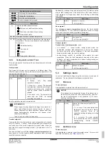
Required concentration of glycol
The required concentration of glycol depends on the lowest
expected outdoor temperature, and on whether you want to protect
the system from bursting or from freezing. To prevent the system
from freezing, more glycol is required.
Add glycol according to the table below.
Lowest expected
outdoor
temperature
Prevent from
bursting
Prevent from
freezing
–5°C
10%
15%
–10°C
15%
25%
–15°C
20%
35%
–20°C
25%
—
–25°C
30%
—
–30°C
35%
—
INFORMATION
▪ Protection against bursting: the glycol will prevent the
piping from bursting, but NOT the liquid inside the
piping from freezing.
▪ Protection against freezing: the glycol will prevent the
liquid inside the piping from freezing.
NOTICE
▪ The required concentration might differ depending on
the type of glycol. ALWAYS compare the requirements
from the table above with the specifications provided by
the glycol manufacturer. If necessary, meet the
requirements set by the glycol manufacturer.
▪ The added concentration of glycol should NEVER
exceed 35%.
▪ If the liquid in the system is frozen, the pump will NOT
be able to start. Mind that if you only prevent the
system from bursting, the liquid inside might still freeze.
▪ When water is at standstill inside the system, the
system is very likely to freeze and get damaged.
Glycol and the maximum allowed water volume
Adding glycol to the water circuit reduces the maximum allowed
water volume of the system. For more information, see the installer
reference guide (topic "To check the water volume and flow rate").
Glycol setting
NOTICE
If glycol is present in the system, setting [E-0D] must be
set to 1. If the glycol setting is NOT set correctly, the liquid
inside the piping can freeze.
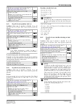
Freeze protection by freeze protection valves
About freeze protection valves
When no glycol is added to the water, you can use freeze protection
valves to drain the water from the system before it can freeze.
▪ Install freeze protection valves (field supply) at all lowest points of
the field piping.
▪ Normally closed valves (located indoors near the piping entry/exit
points) can prevent that all water from indoor piping is drained
when the freeze protection valves open.
NOTICE
When freeze protection valves are installed, set the
minimum cooling setpoint (default=8°C) at least 2°C higher
than the maximum opening temperature of the freeze
protection valve. If lower, freeze protection valves can
open during cooling operation.
For more information, see the installer reference guide.
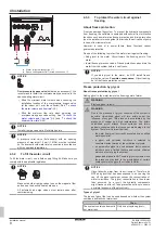
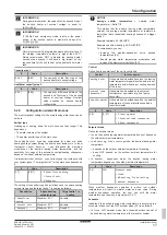
Heater tape (field supply)
1
Install heater tape to the outdoor field piping.
2
Provide external power supply for the heater tape.
NOTICE
▪ For the internal heater tape to operate, the power to the
unit MUST be ON. For this reason, during cold periods,
never disconnect the power, nor turn off the main
switch.
▪ In case of a power failure, power to the heater tape
(both internal and external) will be aborted and the
water circuit will NOT be protected. To guarantee a full
protection, it is always possible to add glycol to the
water circuit or to use freeze protection valves, even
when installing heater tape to the outdoor field piping.
4.3.4
To fill the domestic hot water tank
See the installation manual of the domestic hot water tank.
4.3.5
To insulate the water piping
The piping in the complete water circuit MUST be insulated to
prevent condensation during cooling operation and reduction of the
heating and cooling capacity.
Outdoor water piping insulation
See the installation manual of the outdoor unit, or the installer
reference guide.
4.4
Connecting the electrical wiring
DANGER: RISK OF ELECTROCUTION
WARNING
ALWAYS use multicore cable for power supply cables.
4.4.1
About electrical compliance
Only for the backup heater of the indoor unit
See
"To connect the backup heater power supply"
11].
4.4.2
To connect the electrical wiring to the
indoor unit
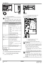
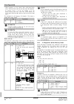
1
Open the switch box so that you can access the back of the
switch box. See
2
Route the wiring as follows:
▪ Enter the unit from the bottom.
▪ Route the wiring via the back of the switch box.
▪ Fix the cables with cable ties to the cable tie mountings at
the back of the switch box.


