


3 Preparation
Installation manual
5
EABH/9W
Daikin Altherma 3 H W
4P644479-1 – 2020.12
3.2.1
To check the water volume and flow rate
Minimum water volume
Check that the total water volume in the installation is minimum 20
litres, the internal water volume of the outdoor unit NOT included.
NOTICE
When circulation in each space heating/cooling loop is
controlled by remotely controlled valves, it is important that
the minimum water volume is guaranteed, even if all of the
valves are closed.
Minimum flow rate
Check that the minimum flow rate in the installation is guaranteed in
all conditions. This minimum flow rate is required during defrost/
backup heater operation. For this purpose, use the overpressure
bypass valve delivered with the unit, and respect the minimum water
volume.
Minimum required flow rate
20 l/min
NOTICE
To guarantee proper operation it is recommended to have
a minimum flow of 28 l/min during DHW.
NOTICE
If glycol was added to the water circuit, and the
temperature of the water circuit is low, the flow rate will
NOT be displayed on the user interface. In this case, the
minimum flow rate can be checked by way of the pump
test (check that the user interface does NOT display error
7H).
NOTICE
When circulation in each or certain space heating loops is
controlled by remotely controlled valves, it is important that
the minimum flow rate is guaranteed, even if all valves are
closed. In case the minimum flow rate cannot be reached,
a flow error 7H will be generated (no heating or operation).
See the installer reference guide for more information.
See the recommended procedure as described in
22].
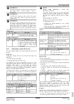
3.2.2
Third-party tank requirements
In case of a third-party tank, the tank shall adhere to the following
requirements:
▪ The heat exchanger coil of the tank is ≥1.05 m².
▪ The tank thermistor must be located above the heat exchanger
coil.
▪ The booster heater must be located above the heat exchanger
coil.
NOTICE
Performance.
Performance data for third-party tanks
CANNOT be provided, and performance CANNOT be
guaranteed.
NOTICE
Configuration.
Configuration of a third-party tank depends
on the size of the heat exchanger coil of the tank. For more
information, see the installer reference guide.
3.3
Preparing electrical wiring
3.3.1
Overview of electrical connections for
external and internal actuators
Item
Description
Wires
Maximum
running
current
Outdoor unit and indoor unit power supply
1
Power supply for
outdoor unit
2+GND
(a)
2
Power supply and
interconnection cable to
indoor unit
3
(g)
3
Power supply for
backup heater
See table below. —
4
Preferential kWh rate
power supply (voltage
free contact)
2
(e)
5
Normal kWh rate power
supply
2
6.3 A
Optional equipment
6
3‑way valve
3
100 mA
(b)
7
Power supply for
booster heater and
thermal protection
(from indoor unit)
4+GND
(c)
8
Power supply for
booster heater (to
indoor unit)
2+GND
13 A
9
Domestic hot water
tank thermistor
2
(d)
10
User interface used as
room thermostat
2
(f)
11
Room thermostat
3 or 4
100 mA
(b)
12
Outdoor ambient
temperature sensor
2
(b)
13
Indoor ambient
temperature sensor
2
(b)
14
Heat pump convector
2
100 mA
(b)
Field supplied components
15
Shut-off valve
2
100 mA
(b)
16
Electricity meter
2 (per meter)
(b)
17
Domestic hot water
pump
2
(b)
18
Alarm output
2
(b)
19
Changeover to external
heat source control
2
(b)
20
Space cool/heat
operation control
2
(b)
21
Power consumption
digital inputs
2 (per input
signal)
(b)
22
Safety thermostat
2
(e)
(a)
Refer to name plate on outdoor unit.
(b)
Minimum cable section 0.75 mm².
(c)
Cable section 2.5 mm².
(d)
The thermistor and connection wire (12 m) are delivered
with the domestic hot water tank.
(e)
Cable section 0.75 mm² till 1.25 mm²; maximum length:
50 m. Voltage-free contact shall ensure the minimum
applicable load of 15 V DC, 10 mA.
(f)
Cable section 0.75 mm² till 1.25 mm²; maximum length:
500 m. Applicable for both single user interface and dual
user interface connection.
(g)
Cable section 1.5 mm².


