


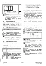


7 Configuration
Installation manual
27
ETVH/9W
Daikin Altherma 3 H HT F
4P644728-1 – 2021.02
Item
Description
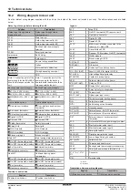
Y1, Y2,
Y3, Y4
Examples of desired tank temperature or leaving water
temperature. The icon corresponds to the heat emitter
for that zone:
▪
: Underfloor heating
▪
: Fan coil unit
▪
: Radiator
▪
: Domestic hot water tank
Possible actions on this screen
Select slope or offset.
Increase or decrease the slope/offset.
When slope is selected: set slope and go to offset.
When offset is selected: set offset.
Confirm changes and return to the submenu.
7.3.4
Using weather-dependent curves
Configure weather-dependent curves as following:
To define the setpoint mode
To use the weather-dependent curve, you need to define the correct
setpoint mode:
Go to setpoint mode …
Set the setpoint mode to …
Main zone – Heating
[2.4]
Main zone
>
Setpoint
mode
WD heating, fixed cooling
OR
Weather dependent
Main zone – Cooling
[2.4]
Main zone
>
Setpoint
mode
Weather dependent
Additional zone – Heating
[3.4]
Additional zone
>
Setpoint mode
WD heating, fixed cooling
OR
Weather dependent
Additional zone – Cooling
[3.4]
Additional zone
>
Setpoint mode
Weather dependent
Tank
[5.B]
Tank
>
Setpoint mode
Restriction:
Only available to
installers.
Weather dependent
To change the type of weather-dependent curve
To change the type for all zones (main + additional) and for the tank,
go to [2.E]
Main zone
>
WD curve type
.
Viewing which type is selected is also possible via:
▪ [3.C]
Additional zone
>
WD curve type
▪ [5.E]
Tank
>
WD curve type
Restriction:
Only available to installers.
To change the weather-dependent curve
Zone
Go to …
Main zone – Heating
[2.5]
Main zone
>
Heating WD
curve
Main zone – Cooling
[2.6]
Main zone
>
Cooling WD
curve
Additional zone – Heating
[3.5]
Additional zone
>
Heating WD curve
Additional zone – Cooling
[3.6]
Additional zone
>
Cooling WD curve
Zone
Go to …
Tank
Restriction:
Only available to
installers.
[5.C]
Tank
>
WD curve
INFORMATION
Maximum and minimum setpoints
You cannot configure the curve with temperatures that are
higher or lower than the set maximum and minimum
setpoints for that zone or for the tank. When the maximum
or minimum setpoint is reached, the curve flattens out.
To fine-tune the weather-dependent curve: slope-offset curve
The following table describes how to fine-tune the weather-
dependent curve of a zone or tank:
You feel …
Fine-tune with slope and
offset:
At regular outdoor
temperatures …
At cold outdoor
temperatures …
Slope
Offset
OK
Cold
↑
—
OK
Hot
↓
—
Cold
OK
↓
↑
Cold
Cold
—
↑
Cold
Hot
↓
↑
Hot
OK
↑
↓
Hot
Cold
↑
↓
Hot
Hot
—
↓
To fine-tune the weather-dependent curve: 2-points curve
The following table describes how to fine-tune the weather-
dependent curve of a zone or tank:
You feel …
Fine-tune with
setpoints:
At regular outdoor
temperatures …
At cold outdoor
temperatures …
Y2
(a)
Y1
(a)
X1
(a)
X2
(a)
OK
Cold
↑
—
↑
—
OK
Hot
↓
—
↓
—
Cold
OK
—
↑
—
↑
Cold
Cold
↑
↑
↑
↑
Cold
Hot
↓
↑
↓
↑
Hot
OK
—
↓
—
↓
Hot
Cold
↑
↓
↑
↓
Hot
Hot
↓
↓
↓
↓
(a)
See
7.4
Settings menu
You can set additional settings using the main menu screen and its
submenus. The most important settings are presented here.
7.4.1
Main zone
Thermostat type
Only applicable in external room thermostat control.
NOTICE
If an external room thermostat is used, the external room
thermostat will control the room frost protection. However,
the room frost protection is only possible if [C.2]
Space
heating/cooling
=
On
.


