236
In Figure 4-112, Select icon
of several dates, all checked items can be edited together.
Now the icon is shown as
. Click
to delete a record type from one period.
In Figure 4-112. Click button
after one date or a holiday, you can see an interface shown
as in Figure 4-113.
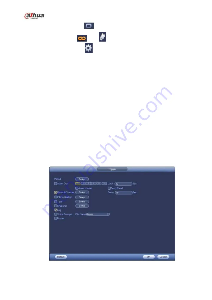
Alarm output: when an alarm occurs, system enables peripheral alarm devices.
Latch: when tripwire complete, system auto delays detecting for a specified time. The value ranges
from 1-300(Unit: second)
Show message: System can pop up a message to alarm you in the local host screen if you enabled
this function.
Alarm upload: System can upload the alarm signal to the network (including alarm center) if you
enabled current function.
Send email: System can send out email to alert you when an alarm occurs.
Record channel: System auto activates tripwire channel(s) to record once an alarm occurs. Please
make sure you have set intelligent record in Schedule interface(Main Menu->Setting->Schedule)
and schedule record in manual record interface(Main Menu->Advanced->Manual Record)
PTZ activation: Here you can set PTZ movement when an alarm occurs. Such as go to preset, tour
&pattern when there is an alarm. Click
“
select
”
button, you can see an interface is shown as in
Record Delay: System can delay the record for specified time after alarm ended. The value ranges
from 10s to 300s.
Tour: Here you can enable tour function when an alarm occurs. System one-window tour.
Snapshot: You can enable this function to snapshot image when a motion detect alarm occurs.
Buzzer: Highlight the icon to enable this function. The buzzer beeps when an alarm occurs.
Figure 4-122
Summary of Contents for NVR1A-4P Series
Page 1: ...Dahua Network Video Recorder User s Manual V 4 3 0 ...
Page 142: ...128 Figure 3 11 3 6 12 NVR42V 8P Series Please refer to Figure 3 12 for connection sample ...
Page 143: ...129 Figure 3 12 ...
Page 157: ...143 Figure 4 15 Step 2 Click device display edit interface See Figure 4 16 ...
Page 220: ...206 Figure 4 93 Figure 4 94 ...
Page 240: ...226 Figure 4 110 Figure 4 111 Figure 4 112 ...
Page 251: ...237 Figure 4 123 Figure 4 124 ...
Page 253: ...239 Figure 4 126 Click draw button to draw the zone See Figure 4 127 ...
Page 257: ...243 Figure 4 130 Click Draw button to draw a zone See Figure 4 131 Figure 4 131 ...
Page 262: ...248 Figure 4 136 Click draw button to draw the zone See Figure 4 137 ...
Page 275: ...261 Figure 4 148 Figure 4 149 ...
Page 276: ...262 Figure 4 150 Figure 4 151 ...
Page 387: ...373 Figure 5 60 Figure 5 61 ...
Page 388: ...374 Figure 5 62 Figure 5 63 ...
Page 412: ...398 Figure 5 96 Figure 5 97 ...


