background image

Lite Series

 | 

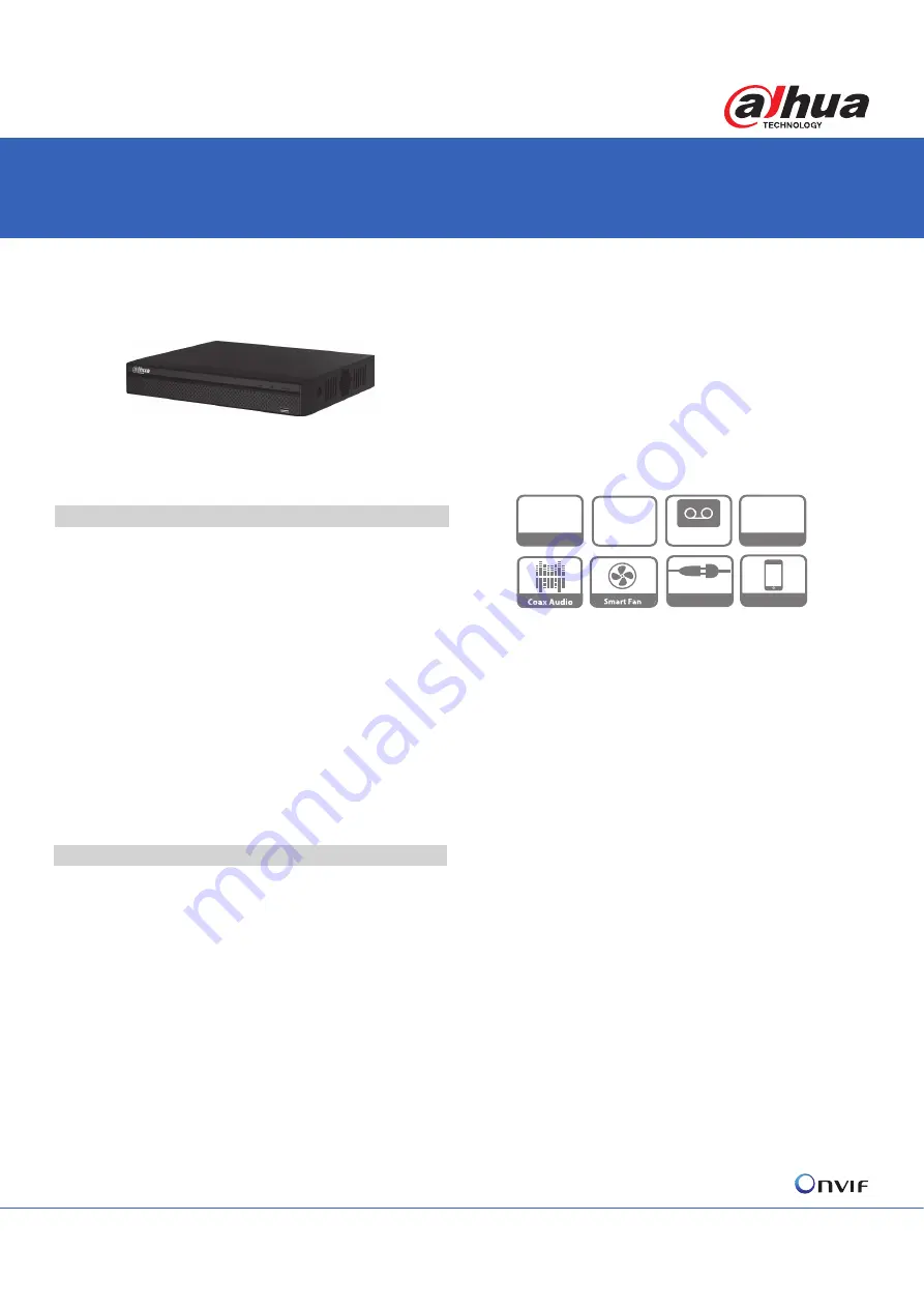
DHI-XVR4104/08/16HS-S2

Smart Fan

dŚĞƐŵĂƌƚĨĂŶĐĂŶĂƵƚŽŵĂƟĐĂůůLJƚƵƌŶŽŶŽƌƚƵƌŶŽīĂĐĐŽƌĚŝŶŐƚŽƚŚĞ
WhƚĞŵƉĞƌĂƚƵƌĞ͘dŚŝƐĨƵŶĐƟŽŶĐĂŶĞīĞĐƟǀĞůLJƌĞĚƵĐĞƚŚĞĨĂŶŶŽŝƐĞƚŽ
ƉƌŽǀŝĚĞĂďĞƩĞƌƵƐĞƌĞdžƉĞƌŝĞŶĐĞǁŚŝůĞĞdžƚĞŶĚŝŶŐƚŚĞůŝĨĞŽĨƚŚĞĨĂŶĂƚƚŚĞ
ƐĂŵĞƟŵĞ͘

Smart Search

dŚŝƐĨƵŶĐƟŽŶŚĞůƉƐLJŽƵŐĞƚŵŽƌĞŵŽƟŽŶĚĞƚĞĐƚǀŝĚĞŽĚƵƌŝŶŐĂƐŚŽƌƚ
ƟŵĞƚŚƌŽƵŐŚĚƌĂǁŝŶŐĂƌĞŐŝŽŶǁŚĞŶƉůĂLJďĂĐŬ͘/ƚŝƐǀĞƌLJƵƐĞĨƵůǁŚĞŶĂŶ
ĞŵĞƌŐĞŶĐLJŽĐĐƵƌƐ͘

Perfect Image Quality

,ŝŐŚƉĞƌĨŽƌŵĂŶĐĞĐŚŝƉƉƌŽǀŝĚĞƐƉĞƌĨĞĐƚŝŵĂŐĞƋƵĂůŝƚLJǁŝƚŚďĞƩĞƌĐŽůŽƌ
ƌĞƉƌŽĚƵĐƟŽŶ͘

P2P


DŽŶŝƚŽƌĂƚĂŶLJƟŵĞĂŶĚĂŶLJǁŚĞƌĞ͘ĂƐŝůLJĂŶĚĐŽŶǀĞŶŝĞŶƚůLJŵĂŶŐĞƚŚĞ
ĚĞǀŝĐĞ͘

ͼ ŵďĞĚĚĞĚƉƌŽĐĞƐƐŽƌ
ͼ ,͘ϮϲϰǀŝĚĞŽĐŽŵƉƌĞƐƐŝŽŶ

· Support 

HDCVI/AHD/TVI/CVBS/IP

ǀŝĚĞŽŝŶƉƵƚƐ

ͼ DĂdžϱͬϭϬͬϭϴĐŚĂŶŶĞůƐ/WĐĂŵĞƌĂŝŶƉƵƚƐ
ͼ >ŽŶŐƚƌĂŶƐŵŝƐƐŝŽŶĚŝƐƚĂŶĐĞŽǀĞƌĐŽĂdžĐĂďůĞ

· Support 1 SATA HDD, up to 8TB

DHI-XVR4104/08/16HS-S2

ϰͬϴͬϭϲŚĂŶŶĞůWĞŶƚĂͲďƌŝĚϳϮϬWŽŵƉĂĐƚϭhŝŐŝƚĂůsŝĚĞŽZĞĐŽƌĚĞƌ

 System Overview

ĂŚƵĂ͕ĂƐĂƚĞĐŚŶŽůŽŐLJůĞĂĚĞƌ͕ŝƐĂůǁĂLJƐƚŚĞĮƌƐƚĞǀĞƌĚĞǀĞůŽƉĞĚƚŚĞ
ƐŚŝŶŝŶŐŶĞǁƚĞĐŚŶŽůŽŐLJŝŶƚŚĞƐĞĐƵƌŝƚLJŝŶĚƵƐƚƌLJ͕ĂŶĚƚŽĚĂLJǁĞƉƌĞƐĞŶƚ
ysZͲ^Ϯ^ĞƌŝĞƐ͘ƐƚŚĞƉĞƌĨĞĐƚƐŽůƵƟŽŶƚŽƵƉŐƌĂĚĞĞdžŝƐƟŶŐǀŝĚĞŽ
ƐƵƌǀĞŝůůĂŶĐĞƐLJƐƚĞŵƐ͕ysZƐƵƉƉŽƌƚƐƉĞŶƚĂͲďƌŝĚĂĐĐĞƐƐƚĞĐŚŶŽůŽŐLJƐƵĐŚ
ĂƐ,s/͕,͕ds/͕s^ĂŶĚ/WƚŽĞīŽƌƚůĞƐƐůLJŝŶƚĞŐƌĂƚĞǁŝƚŚƉŽƉƵůĂƌ
ŝŶĚƵƐƚƌLJĨŽƌŵĂƚƐ͕ŽīĞƌŝŶŐĂŶĂīŽƌĚĂďůĞƐŽůƵƟŽŶůŽĂĚĞĚǁŝƚŚŇĞdžŝďůĞ
ŽƉƟŽŶƐ͘/ƚƐƵƉƉŽƌƚƐƵƉƚŽϰͬϴͬϭϲĐŚĂŶŶĞůƐŽĨ,s/ͬ,ͬds/ͬs^
ŝŶƉƵƚƐ͕ĂŶĚϭͬϮͬϮĐŚĂŶŶĞůƐ/WĐĂŵĞƌĂĂĚĚŝƟŽŶĂůůLJ͕ϭϲĐŚĂŶŶĞůƐůŽĐĂů
ůŝǀĞͲǀŝĞǁĐŚĂŶŶĞůƐ͕ĂŶĚϭϲƉůĂLJďĂĐŬĐŚĂŶŶĞůƐ͘

ĞƐŝŐŶĞĚĂƐĂĨƵůůĐŽŵƉĂƟďŝůŝƚLJƉƌŽĚƵĐƚ͕ysZŝƐĂďůĞƚŽƉƌŽǀŝĚĞĞŶĚ
ƵƐĞƌƚŚĞƐŝŵƉůŝĐŝƚLJŽĨĂŶĂůŽŐƐLJƐƚĞŵ͕ŶĂŵĞůLJůŽǁĞƌƐLJƐƚĞŵĐŽƐƚ͕ƐŝŵƉůĞ
ŝŶƐƚĂůůĂƟŽŶĂŶĚƵƐĞŽĨĞdžŝƐƟŶŐĐĂďůĞ͘/ƚŝƐŝĚĞĂůĨŽƌĂǁŝĚĞƌĂŶŐĞŽĨ
ĂƉƉůŝĐĂƟŽŶƐƐƵĐŚĂƐƉƵďůŝĐƐĂĨĞƚLJ͕ƌĞƚĂŝůƐƚŽƌĞ͕ƚƌĂŶƐƉŽƌƚĂƟŽŶ͕ŚŽŵĞ
ƉƌŽƚĞĐƟŽŶĂŶĚĞĚƵĐĂƟŽŶ͘

&ƵŶĐƟŽŶƐ

HDCVI/AHD/TVI/CVBS/IP Auto-detect

dŚĞysZĐĂŶĂƵƚŽƌĞĐŽŐŶŝnjĞƚŚĞƐŝŐŶĂůŽĨĨƌŽŶƚͲĐĂŵĞƌĂǁŝƚŚŽƵƚĂŶLJ
ƐĞƫŶŐ͘/ƚŵĂŬĞƐŽƉĞƌĂƟŽŶŵŽƌĞĨƌŝĞŶĚůLJĂŶĚĐŽŶǀĞŶŝĞŶƚ͘

ϱDWZĞƐŽůƵƟŽŶ

( XVR4108/16HS-S2 )

dŚĞysZƐƵƉƉŽƌƚƐƵƉƚŽϱDW,ƌĞƐŽůƵƟŽŶ;ϮϱϲϬdžϭϵϮϬͿ/WŝŶƉƵƚĨŽƌ
ƌĞĐŽƌĚŝŶŐ͕ůŝǀĞǀŝĞǁŝŶŐ͘

Coaxial Audio/Upgrade/Alarm

dŚĞŝŶƚĞŐƌĂƚĞĚĚĞƐŝŐŶĐĂŶƌĞĚƵĐĞǁŝƌŝŶŐƚƌŽƵďůĞƐǁŚŝĐŚŵĂŬĞƐŝƚŵƵĐŚ
ŵŽƌĞĐŽƐƚͲĞīĞĐƟǀĞĂŶĚĐŽŶǀĞŶŝĞŶƚĨŽƌŝŶƐƚĂůůĂƟŽŶ͘

 Series

Lite

      Plug&Play

P2P

1080p

HDMI / VGA

   4/8/16CH

H.264

www.PadVokam.by

www.dahuasecurity.by

Summary of Contents for Lite DHI-XVR4104/08/16HS-S2

Page 1: ...ĂLJ ǁĞ ƉƌĞƐĞŶƚ ysZͲ Ϯ ĞƌŝĞƐ Ɛ ƚŚĞ ƉĞƌĨĞĐƚ ƐŽůƵƟŽŶ ƚŽ ƵƉŐƌĂĚĞ ĞdžŝƐƟŶŐ ǀŝĚĞŽ ƐƵƌǀĞŝůůĂŶĐĞ ƐLJƐƚĞŵƐ ysZ ƐƵƉƉŽƌƚƐ ƉĞŶƚĂͲďƌŝĚ ĂĐĐĞƐƐ ƚĞĐŚŶŽůŽŐLJ ƐƵĐŚ ĂƐ s ds s ĂŶĚ W ƚŽ ĞīŽƌƚůĞƐƐůLJ ŝŶƚĞŐƌĂƚĞ ǁŝƚŚ ƉŽƉƵůĂƌ ŝŶĚƵƐƚƌLJ ĨŽƌŵĂƚƐ ŽīĞƌŝŶŐ ĂŶ ĂīŽƌĚĂďůĞ ƐŽůƵƟŽŶ ůŽĂĚĞĚ ǁŝƚŚ ŇĞdžŝďůĞ ŽƉƟŽŶƐ ƚ ƐƵƉƉŽƌƚƐ ƵƉ ƚŽ ϰ ϴ ϭϲ ĐŚĂŶŶĞůƐ ŽĨ s ds s ŝŶƉƵƚƐ ĂŶĚ ϭ Ϯ Ϯ ĐŚĂŶŶĞůƐ W ĐĂŵĞƌĂ ĂĚĚŝƟŽŶĂůůLJ ϭϲ ĐŚĂŶŶĞůƐ ůŽĐĂů ůŝǀĞͲǀŝĞǁ ĐŚĂŶŶĞůƐ ĂŶĚ ...

Page 2: ...DdW EdW W E W ŝůƚĞƌ WWWŽ E dW ůĂƌŵ ĞƌǀĞƌ WϮW W ĞĂƌĐŚ ƵƉƉŽƌƚ ĂŚƵĂ W ĐĂŵĞƌĂ sZ Es ĞƚĐ Ϳ DĂdž hƐĞƌ ĐĐĞƐƐ 128 users Smart Phone ŝWŚŽŶĞ ŝWĂĚ ŶĚƌŽŝĚ ŶƚĞƌŽƉĞƌĂďŝůŝƚLJ KEs Ϯ ϰϮ ŽŶĨŽƌŵĂŶƚ sŝĚĞŽ ĞƚĞĐƟŽŶ ĂŶĚ ůĂƌŵ dƌŝŐŐĞƌ ǀĞŶƚƐ ZĞĐŽƌĚŝŶŐ Wd dŽƵƌ sŝĚĞŽ WƵƐŚ ŵĂŝů dW ŶĂƉƐŚŽƚ ƵnjnjĞƌ ĂŶĚ ĐƌĞĞŶ dŝƉƐ sŝĚĞŽ ĞƚĞĐƚŝŽŶ DŽƚŝŽŶ ĞƚĞĐƚŝŽŶ D ŽŶĞƐ ϯϵϲ ϮϮ п ϭϴͿ sŝĚĞŽ ŽƐƐ dĂŵƉĞƌŝŶŐ ĂŶĚ ŝĂŐŶŽƐŝƐ ůĂƌŵ ŝŶƉƵƚ E ZĞůĂLJ KƵƚƉƵƚ E WůĂLJďĂĐŬ...

Page 3: ...ŝŐŝƚĂů sŝĚĞŽ ZĞĐŽƌĚĞƌ DHI XVR4108HS S2 ϴ ŚĂŶŶĞů WĞŶƚĂͲďƌŝĚ ϳϮϬW ŽŵƉĂĐƚ ϭh ŝŐŝƚĂů sŝĚĞŽ ZĞĐŽƌĚĞƌ DHI XVR4116HS S2 ϭϲ ŚĂŶŶĞů WĞŶƚĂͲďƌŝĚ ϳϮϬW ŽŵƉĂĐƚ ϭh ŝŐŝƚĂů sŝĚĞŽ ZĞĐŽƌĚĞƌ ŝŵĞŶƐŝŽŶƐ ŵŵͿ Rear Panel DHI XVR4104HS S2 1 2 3 4 5 6 7 8 9 DHI XVR4108HS S2 1 2 3 4 5 6 7 8 9 DHI XVR4116HS S2 1 s K E 6 Z ϰϴϱ ŶƚĞƌĨĂĐĞ 2 h K E Z ŽŶŶĞĐƚŽƌ ϳ USB Interface ϯ AUDIO OUT RCA Connector 8 ϭϮs WŽǁĞƌ ŶƉƵƚ 4 HDMI Interfa...

Page 4: ...onfiguring a network Smart IR The camera is designed with microcrystalline LED IR illumination for best lowlight performance Smart IR is a technology to ensure brightness uniformity in B W image under low illumination Dahua s unique Smart IR adjusts to the intensity of camera s infrared LEDs to compensate for the distance of an object and prevents IR LEDs from overexposing images as the object com...

Page 5: ...280 720 Frame Rate 25 30fps 720P Video Output 1 channel BNC high definition video output CVBS video output Can switch Day Night Auto ICR Manual OSD Menu Multi language BLC Mode BLC HLC DWDR WDR DWDR Gain Control AGC Noise Reduction 2D White Balance Auto Manual Smart IR Auto Manual Certifications Certifications CE EN55032 EN55024 EN50130 4 FCC CFR 47 FCC Part 15 subpartB ANSI C63 4 2014 UL UL60950 ...

Page 6: ...RP 2 8mm 1MP HDCVI IR Eyeball Camera PAL DH HAC HDW1000RP 3 6mm DH HAC HDW1000RN 2 8mm 1MP HDCVI IR Eyeball Camera NTSC DH HAC HDW1000RN 3 6mm Accessories PFA122 Junction box For use alone or with PFA152 pole mount PFA152 Pole mount For use with PFA122 junction box PFM820 UTC Controller Dimensions mm inch Accessories Optional PFA122 Junction box PFA152 Pole mount Junc on Mount Pole Mount PFB122 PF...

Page 7: ...at least 3X weight of the camera Note If you want to install in the wood surface expansion bolts are not necessary The screw depth shall reserve 8mm 10mm to secure the bracket Please refer to Figure 1 1 for installation of Model A Figure 1 1 Please refer to Figure 1 2 for installation of Model B Figure 1 2 ...

Page 8: ...lease refer to Figure 1 3 for the installation of Model C Figure 1 3 Please refer to Figure 1 4 for the installation of Model D Figure 1 4 Please refer to Figure 1 5 and 1 6 for the installation of Model E ...

Page 9: ...3 Figure 1 5 Figure 1 6 Please refer to Figure 1 7 for the installation of Model F ...

Page 10: ...4 Figure 1 7 Note This manual is for reference only Please visit our website or contact your local service engineer for more information ...

Page 11: ...HDCVI Camera User s Manual Version 1 0 2 ...

Page 12: ... 1 2 Features 1 2 Device Framework 2 3 Installation 5 3 1 Installation for Model A 5 3 2 Installation for Model B 6 3 3 Installation for Model C 7 3 4 Installation for Model D 8 3 5 Installation for Model E 9 4 Menu 11 4 1 HCVR Settings 11 4 2 Menu Operation 11 ...

Page 13: ... We are not liable for any problems caused by unauthorized modification or attempted repair Environment Please don t aim the device at strong light such as lighting sunlight and so on to focus otherwise it may cause overexposure It is not the device malfunction which will affect the longevity of CCD or CMOS Please transport use and store the device within the range of allowed humidity and temperat...

Page 14: ...water drop or oil gently to make it dry then use oil free cotton cloth or paper soaked with alcohol or detergent to wipe from the lens center to outward It is ok to change the cloth and wipe several times if it is not clean enough Warning Please use the standard accessories provided by manufacturer and make sure the device is installed and fixed by professional engineers Please prevent the device ...

Page 15: ...m For 1080P series support 75 3 coaxial cable transmission without any loss The distance is over 500m Support HDCVI HD SD output Support ICR switch to realize surveillance both in the daytime and at night Support OSD menu adjustment parameters Support smart IR function Support DWDR function Support High speed long distance real time transmission Support DC12V power supplying Support IP67 complianc...

Page 16: ...e Figure 2 1 for the dimension of model A Figure 2 1 See Figure 2 2 for the structure components of model A Figure 2 2 See Figure 2 3 for the dimension of model B Figure 2 3 See Figure 2 4 for the structure components model B ...

Page 17: ...re 2 5 for the dimension of model C Figure 2 5 See Figure 2 6 for the structure components of model C Figure 2 6 See Figure 2 7 for the dimension of model D Figure 2 7 See Figure 2 8 for the structure components of model D ...

Page 18: ...4 Figure 2 8 See Figure 2 9 for the dimension of model E Figure 2 9 See Figure 2 10 for the structure components of model E Figure 2 10 ...

Page 19: ...ed film on the surface of transparent cover before installation debugging is over which is to avoid damage during installation please do not touch the dome cover in order to avoid leaving a mark after the absorbed film is removed The installation figures below are for reference only 3 1 Installation for Model A Figure 3 1 Step 1 Hold the decoration ring tightly and unscrew the pedestal anticlockwi...

Page 20: ...g location connect the video output port of device cable to back end encoding device and connect power port to power adjust lens focal length to make image clear via focus tool after the image is displayed on the back end coding device finally rotate the decoration ring firmly So far the device installation and cable connection are completed you can check the image via back end coding device 3 2 I...

Page 21: ... bolt fixing holes of the installation surface insert the self tapping screws into the expansion bolts and fasten them firmly to fix the pedestal on the installation surface if it is top outlet pull the cable through the outlet hole on the installation surface after the pedestal is fixed firmly Step 5 Put the enclosure and dome body into the pedestal rotate enclosure and dome body to a proper moni...

Page 22: ...xpansion bolt fixing holes of the installation surface insert the self tapping screws into the expansion bolts and fasten them firmly to fix the pedestal on the installation surface if it is top outlet pull the cable through the outlet hole on the installation surface after the pedestal is fixed firmly Step 5 Rotate the decoration ring and fix it slightly rotate the compression cover and dome body...

Page 23: ...n if it is side cable outlet then pull the cable through the side outlet cable slot Align the bolt fixing holes of the device pedestal with the expansion bolt fixing holes of the installation surface insert the self tapping screws into the expansion bolts and fasten them firmly to fix the pedestal on the installation surface if it is top outlet pull the cable through the outlet hole on the install...

Page 24: ... fixing holes of the installation surface insert the self tapping screws into the expansion bolts and fasten them firmly to fix the pedestal on the installation surface if it is top outlet pull the cable through the outlet hole on the installation surface after the pedestal is fixed firmly Step 5 Put the enclosure and dome body into the pedestal insert locking screws clockwise and fix them slightl...

Page 25: ...nu Setting System PTZ you need to select the channel number for access and set control mode as HDCVI and the protocol as HD CVI Click Save button to save current setup See Figure 4 1 Figure 4 1 4 2 Menu Operation Click the right mouse button and select PTZ Control then you will see the PTZ Setup menu which is as shown in Figure 4 2 and Figure 4 3 Figure 4 2 ...

Page 26: ... or enter the OSD menu for to switchover between HD SD video output Note This manual is for reference only Slight difference may be found in the user interface All the designs and software here are subject to change without prior written notice All trademarks and registered trademarks mentioned are the properties of their respective owners If there is any uncertainty or controversy please refer to...

Reviews: