background image

Quick Start Guide 

1 Introduction 

1.1 Cable 


Waterproof all the cable joints with insulating tape and waterproof tape to avoid short circuit and 
water damage. For the detailed operation, see FAQ manual. 

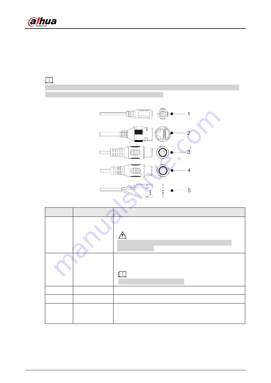
Figure 1-1 Cables 


Table 1-1 Cable information 

No. 

Port Name 

Description 

Power port 

Inputs 12 VDC power supply, and supports power supply at the 

same time. 


Camera abnormity or damage could occur if power is not 

supplied correctly. 

Ethernet port 

  Connects to network with network cable. 

  Provides power to the camera with PoE. 


PoE is available on select models. 

Audio input 

Connects to sound-pick-up device to receive audio signal. 

Audio outpot 

Connects to speakers to output audio signal. 

Alarm I/O 

Includes alarm signal input and output ports, and the number 

of I/O ports might vary on different devices. For detailed 

information, see Table 1-2. 

Summary of Contents for IPC-HFW2831T-ZS-27135-S2

Page 1: ...Bullet Network Camera Quick Start Guide ZHEJIANG DAHUA VISION TECHNOLOGY CO LTD V1 0 2 ...

Page 2: ... need to be in compliance with your local privacy protection laws and regulations to protect the legitimate rights and interests of other people by implementing measures which include but are not limited Providing clear and visible identification to inform people of the existence of the surveillance area and provide required contact information About the Manual The manual is for reference only Sli...

Page 3: ... the reader software or try other mainstream reader software if the manual in PDF format cannot be opened All trademarks registered trademarks and the company names in the manual are the properties of their respective owners Please visit our website contact the supplier or customer service if any problems occur while using the device If there is any uncertainty or controversy we reserve the right ...

Page 4: ...afety code and standards and check whether the power supply is correct before operating the device Please follow the electrical requirements to power the device When selecting the power adapter the power supply must conform to the requirements of ES1 in IEC 62368 1 standard and be no higher than PS2 Please note that the power supply requirements are subject to the device label We recommend using t...

Page 5: ...point where they exit from the device Do not directly touch the photosensitive CMOS Use an air blower to clean the dust or dirt on the lens The dome cover is an optical component Do not directly touch or wipe the surface of the cover when using it There might be a risk of electrostatic discharge on the dome cover Power off the device when installing the cover after the camera finishes adjustment D...

Page 6: ...ot use volatile solvents such as ethyl alcohol benzene diluent or abrasive detergents on the device to avoid damaging the coating and degrading the performance of the device The dome cover is an optical component When it is contaminated with dust grease or fingerprints use degreasing cotton moistened with a little ether or a clean soft cloth dipped in water to gently wipe it clean An air gun is us...

Page 7: ...twork Configuration 4 2 1 Initializing the Camera 4 2 2 Changing Device IP Address 6 2 3 Logging in to Web Page 7 3 Installation 8 3 1 Packing List 8 3 2 Dimensions 8 3 3 Installing the Camera 9 3 3 1 Installation Method 9 3 3 2 Installing SD Card 9 3 3 3 Attaching the Camera 9 3 3 4 Optional Installing Waterproof Connector 11 3 3 5 Adjusting Lens Angle 11 ...

Page 8: ...orts power supply at the same time Camera abnormity or damage could occur if power is not supplied correctly 2 Ethernet port Connects to network with network cable Provides power to the camera with PoE PoE is available on select models 3 Audio input Connects to sound pick up device to receive audio signal 4 Audio outpot Connects to speakers to output audio signal 5 Alarm I O Includes alarm signal ...

Page 9: ...and being grounded Device collects logic 1 when input signal is connected to 3 V to 5 V or idling Device collects logic 0 when input signal is grounded Figure 1 2 Alarm input Step 2 Connect alarm output device to the alarm output end of the I O port The alarm output is open drain output which works in the following modes Mode A Level application Alarm outputs high and low level and the alarm outle...

Page 10: ...s corresponding to the alarm input end of the I O port There will be high level and low level alarm signal generated by the alarm input device when alarm occurs Set the input mode to NO default if the alarm input signal is logic 0 and to NC if the alarm input signal is logic 1 The alarm output on the web page is corresponding to the alarm output end of the device which is also the alarm output end...

Page 11: ...a Step 1 Double click ConfigTool exe to open the tool Step 2 Click Modify IP Step 3 Click Search Setting Figure 2 1 Setting Step 4 Select the searching way Current Segment Search default Select the Current Segment Search checkbox Enter the username in the Username box and the password in the Password box The system will search for devices accordingly Other Segment Search Select the Other Segment S...

Page 12: ...lized and then click Initialize If you do not provide the linked information for password reset you can reset the password only through XML file When initializing multiple cameras ConfigTool initializes all cameras based on the password reset mode of the first selected camera Figure 2 2 Password setting Step 8 Set and confirm the password of the devices then enter a valid email address and then cl...

Page 13: ...one time This section is based on changing IP addresses in batches Changing IP addresses in batches is available only when the corresponding cameras have the same login password Step 1 Follow Step1 to Step5 in 2 1 Initializing the Camera to search for cameras on your network segment After clicking Search Setting enter the username and password and make sure that they are the same as what you set d...

Page 14: ...es from DHCP server when you select DHCP Step 4 Click OK 2 3 Logging in to Web Page Step 1 Open IE browser enter the IP address of the device in the address bar and then press the Enter key If the setup wizard is displayed finish the settings as instructed Step 2 Enter the username and password in the login box and then click Login Step 3 For the first time login click Click Here to Download Plugi...

Page 15: ...the installation such as electric drill is not provided in the package The operation manual and related tool information are contained in the disk or the QR code Figure 3 1 Packing list 3 2 Dimensions Figure 3 2 Dimensions Model A mm inch Figure 3 3 Dimensions Model B mm inch ...

Page 16: ...card slot is available on select models Disconnect the power before installing or removing the SD card Press the reset button for 10 seconds to reset the device Figure 3 5 Install SD card 3 3 3 Attaching the Camera Make sure that the mounting surface is strong enough to hold at least three times the weight of the camera and bracket ...

Page 17: ...Quick Start Guide 10 Figure 3 6 Cable going through the side cable tray Figure 3 7 Cable going through the mounting surface ...

Page 18: ...l Installing Waterproof Connector This part is needed only when a waterproof connector comes with the camera and the camera is used outdoors Figure 3 8 Install waterproof connector 3 3 5 Adjusting Lens Angle Figure 3 9 Adjust lens angle ...

Page 19: ...Quick Start Guide ...

Reviews: