54
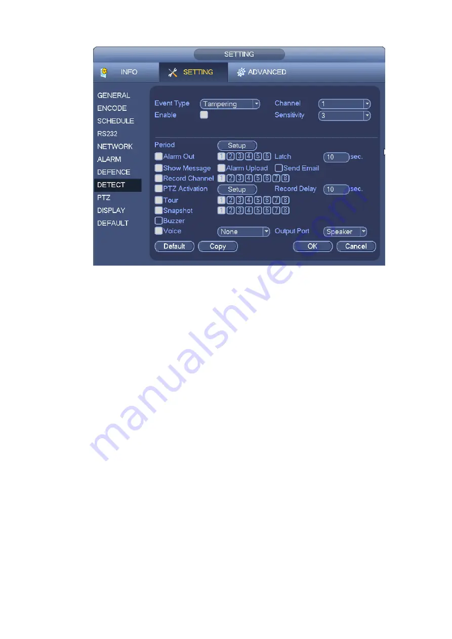
Figure 4-51
4.12
Alarm
You can follow the steps listed below to set.
a) You can connect the external alarm port from the rear panel of the device. Usually the vehicle
left-turn, right-turn, brake and door signal information and etc can be input to the device via the
alarm input device.
b) In the main menu, from Setting to Alarm, you can see alarm setup interface. See Figure 4-53.
c) This series product support 6-channel level alarm information. You can set its actual alarm
name such as left-turn, right-turn on the Alarm Name item. Check the Overlay button, you can
overlay corresponding alarm information on the record file.
d) If the alarm signal is 12V/24V voltage, the trigger type shall be high v alid. If the alarm signal is
ground signal, the trigger type shall be low valid.
e) The normal open means the alarm signal is usually disconnect, system can generate an alarm
when the alarm signal closed. The normal close means the alarm signal is usually con nect,
system can generate an alarm when the alarm signal disconnected.
f)
You need to set for each alarm channel on the Alarm in item if the device has connected
several alarm channels.
Alarm in: Here is for you to select channel number.
Event type: There are two types. IPC external (Figure 4-52)/IPC offline alarm (Figure 4-53).
IPC external alarm: It is the on-off alarm signal from the front-end device and can activate the
local ATM DVR.
IPC offline alarm: Once you select this item, system can generate an alarm when the front -end
IPC disconnects with the local ATM DVR. The alarm can activate record, PTZ, snap and etc.
The alarm can last until the IPC and the ATM DVR connection resumes.
For general series product, it has another type alarm : network input alarm.
Summary of Contents for DVR0X04AH-VD-E
Page 1: ...ATM DVR Series User s Manual Version 1 1 0 ...
Page 24: ...15 Drag mouse Select motion detection zone Select privacy mask zone ...
Page 60: ...51 Figure 4 44 Figure 4 45 Figure 4 46 ...
Page 61: ...52 Figure 4 47 Figure 4 48 Figure 4 49 ...
Page 79: ...70 Figure 5 13 Figure 5 14 Figure 5 15 ...
Page 101: ...92 Figure 5 44 Figure 5 45 ...
Page 103: ...94 Figure 5 47 Figure 5 48 ...
Page 123: ...114 Switch user you can use another account to log in Figure 5 78 ...
Page 156: ...147 Figure 6 51 Figure 6 52 Figure 6 53 Figure 6 54 ...
Page 175: ...166 Figure 6 85 Figure 6 86 ...
Page 200: ...191 Maxtor DiamondMax 20 STM3250820AS 250G SATA ...


