


445
7 FAQ
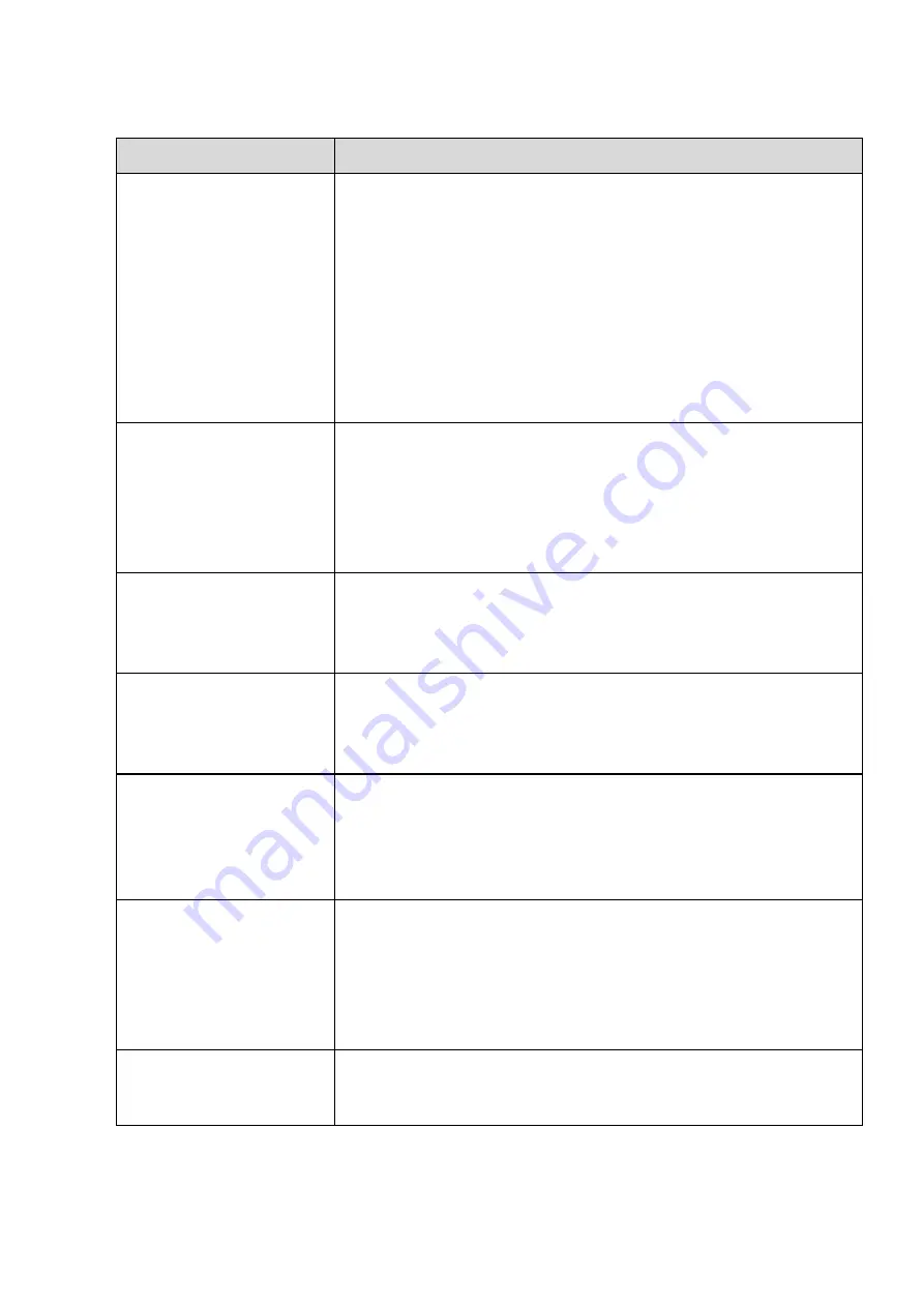
Questions
Solutions
NVR cannot boot up
properly.
Input power is not correct.
Power connection is not correct.
Power switch button is damaged.
Program upgrade is wrong.
HDD malfunction or something wrong with HDD ribbon.
Seagate DB35.1, DB35.2, SV35 or Maxtor 17-g has compatibility
problem. Please upgrade to the latest version to solve this
problem.
Front panel error.
Main board is damaged.
NVR often automatically
shuts down or stops
running.
Input voltage is not stable or it is too low.
HDD malfunction or something wrong with the ribbon.
Button power is not enough.
Front video signal is not stable.
Working environment is too harsh, too much dust.
Hardware malfunction.
System cannot detect
hard disk.
HDD is broken.
HDD ribbon is damaged.
HDD cable connection is loose.
Main board SATA port is broken.
There is no video output
whether it is one-channel,
multiple-channel or
all-channel output.
Program is not compatible. Please upgrade to the latest version.
Brightness is 0. Please restore factory default setup.
Check your screen saver.
NVR hardware malfunctions.
I cannot search local
records.
HDD ribbon is damaged.
HDD is broken.
Upgraded program is not compatible.
The recorded file has been overwritten.
Record function has been disabled.
Video is distorted when
searching local records.
Video quality setup is too low.
Program read error, bit data is too small. There is mosaic in the full
screen. Please restart the NVR to solve this problem.
HDD data ribbon error.
HDD malfunction.
NVR hardware malfunctions.
Time
display
is
not
correct.
Setup is not correct
Battery contact is not correct or voltage is too low.
Crystal is broken.
Summary of Contents for DHI-NVR5224-24P-4KS2
Page 1: ...Network Video Recorder User s Manual V4 3 2...
Page 136: ...124 Figure 3 5 3 6 6 NVR42N Series Please refer to Figure 3 6 for connection sample Figure 3 6...
Page 140: ...128 Figure 3 11 3 6 12 NVR42V 8P Series Please refer to Figure 3 12 for connection sample...
Page 141: ...129 Figure 3 12...
Page 155: ...143 Figure 4 15 Step 2 Click device display edit interface See Figure 4 16...
Page 218: ...206 Figure 4 93 Figure 4 94...
Page 238: ...226 Figure 4 110 Figure 4 111 Figure 4 112...
Page 249: ...237 Figure 4 123 Figure 4 124...
Page 251: ...239 Figure 4 126 Click draw button to draw the zone See Figure 4 127...
Page 255: ...243 Figure 4 130 Click Draw button to draw a zone See Figure 4 131 Figure 4 131...
Page 260: ...248 Figure 4 136 Click draw button to draw the zone See Figure 4 137...
Page 273: ...261 Figure 4 148 Figure 4 149...
Page 274: ...262 Figure 4 150 Figure 4 151...
Page 384: ...372 Figure 5 60 Figure 5 61...
Page 385: ...373 Figure 5 62 Figure 5 63...
Page 409: ...397 Figure 5 96 Figure 5 97...