


276
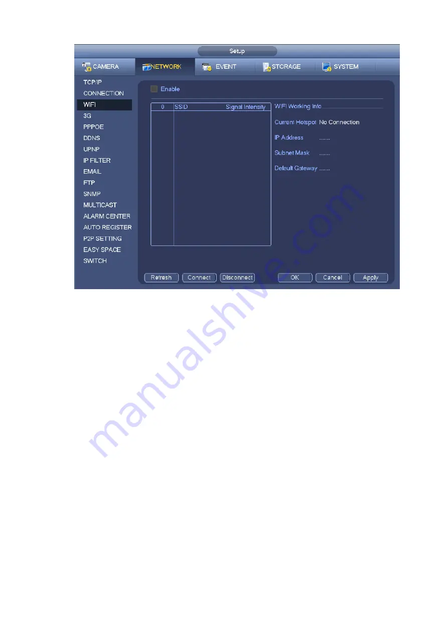
Figure 4-167
WIFI working status: Here you can view current connection status.
Please note:
After successful connection, you can see WIFI connection icon at the top right corner of the preview
interface.
When the hotspot verification type is WEP, system displays as AUTO since the device cannot detect
its encryption type.
System does not support verification type WPA and WPA2. The display may become abnormal for
the verification type and encryption type.
After device successfully connected to the WIFI, you can view the hotspot name, IP address, subnet
mask, default gateway and etc. Right now system support TOTOLINK_N2200UP module.
4.8.1.5 3G
3G setup interface is shown as below. See Figure 4-168.
Please refer to the following contents for the parameter information.
Pane 1: Display 3G signal intensity after you enabled 3G function.
Pane 2: Display 3G module configuration information after you enabled 3G function.
Pane 3: Display 3G module status information after you enabled 3G function.
It is to display current wireless network signal intensity such as EVDO, CDMA1x, WCDMA, WCDMA,
EDGE and etc.
3G module: It is to display current wireless network adapter name.
3G Enable/Disable: Check the box here to enable 3G module.
Network type: There are various network types for different 3G network modules. You can select
according to your requirements.
Summary of Contents for DHI-NVR5224-24P-4KS2
Page 1: ...Network Video Recorder User s Manual V4 3 2...
Page 136: ...124 Figure 3 5 3 6 6 NVR42N Series Please refer to Figure 3 6 for connection sample Figure 3 6...
Page 140: ...128 Figure 3 11 3 6 12 NVR42V 8P Series Please refer to Figure 3 12 for connection sample...
Page 141: ...129 Figure 3 12...
Page 155: ...143 Figure 4 15 Step 2 Click device display edit interface See Figure 4 16...
Page 218: ...206 Figure 4 93 Figure 4 94...
Page 238: ...226 Figure 4 110 Figure 4 111 Figure 4 112...
Page 249: ...237 Figure 4 123 Figure 4 124...
Page 251: ...239 Figure 4 126 Click draw button to draw the zone See Figure 4 127...
Page 255: ...243 Figure 4 130 Click Draw button to draw a zone See Figure 4 131 Figure 4 131...
Page 260: ...248 Figure 4 136 Click draw button to draw the zone See Figure 4 137...
Page 273: ...261 Figure 4 148 Figure 4 149...
Page 274: ...262 Figure 4 150 Figure 4 151...
Page 384: ...372 Figure 5 60 Figure 5 61...
Page 385: ...373 Figure 5 62 Figure 5 63...
Page 409: ...397 Figure 5 96 Figure 5 97...