


258
Figure 4-146
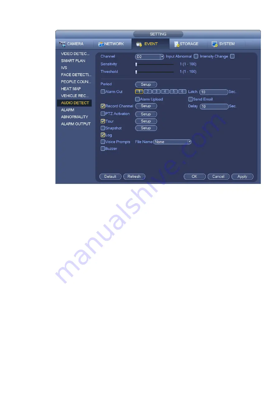
4.7.9
Alarm Settings
In the main menu, from Setting->Event->Alarm, you can see alarm setup interface.
Alarm in: Here is for you to select channel number.
In the main menu, from Setting->Event->Alarm, you can see alarm setup interface. See Figure 4-147.
There are four alarm types. See Figure 4-147 to Figure 4-150.
Local alarm: After connect the alarm device to the NVR alarm input port, system can trigger the
corresponding alarm operations when there is alarm signal from the alarm input port to the NVR.
Network alarm: NVR trigger corresponding alarm operations when it receives the alarm signal via the
network transmission.
IPC external alarm: When the network camera connected peripheral device has triggered an alarm ,
it can upload the alarm signal to the NVR via the network transmission. The system can trigger the
corresponding alarm operations.
IPC offline alarm: When the network connection between the NVR and the network camera is off, the
system can trigger the corresponding alarm operations.
Enable: Please you need to highlight this button to enable current function.
Type: normal open or normal close.
Period: Click set button, you can see an interface is shown as in Figure 4-152. There are two ways
for you to set periods. There are max 6 periods in one day. There are four record types: regular,
motion detection (MD), Alarm, MD & alarm.
Summary of Contents for DHI-NVR5224-24P-4KS2
Page 1: ...Network Video Recorder User s Manual V4 3 2...
Page 136: ...124 Figure 3 5 3 6 6 NVR42N Series Please refer to Figure 3 6 for connection sample Figure 3 6...
Page 140: ...128 Figure 3 11 3 6 12 NVR42V 8P Series Please refer to Figure 3 12 for connection sample...
Page 141: ...129 Figure 3 12...
Page 155: ...143 Figure 4 15 Step 2 Click device display edit interface See Figure 4 16...
Page 218: ...206 Figure 4 93 Figure 4 94...
Page 238: ...226 Figure 4 110 Figure 4 111 Figure 4 112...
Page 249: ...237 Figure 4 123 Figure 4 124...
Page 251: ...239 Figure 4 126 Click draw button to draw the zone See Figure 4 127...
Page 255: ...243 Figure 4 130 Click Draw button to draw a zone See Figure 4 131 Figure 4 131...
Page 260: ...248 Figure 4 136 Click draw button to draw the zone See Figure 4 137...
Page 273: ...261 Figure 4 148 Figure 4 149...
Page 274: ...262 Figure 4 150 Figure 4 151...
Page 384: ...372 Figure 5 60 Figure 5 61...
Page 385: ...373 Figure 5 62 Figure 5 63...
Page 409: ...397 Figure 5 96 Figure 5 97...